LOCK MECHANISM FOR AUTOMOBILES.
A cone with a free-spinning skirt: anti-wrench thinking, 1916 style
A cone-shaped shackle lock for automobiles
⚿ How it works
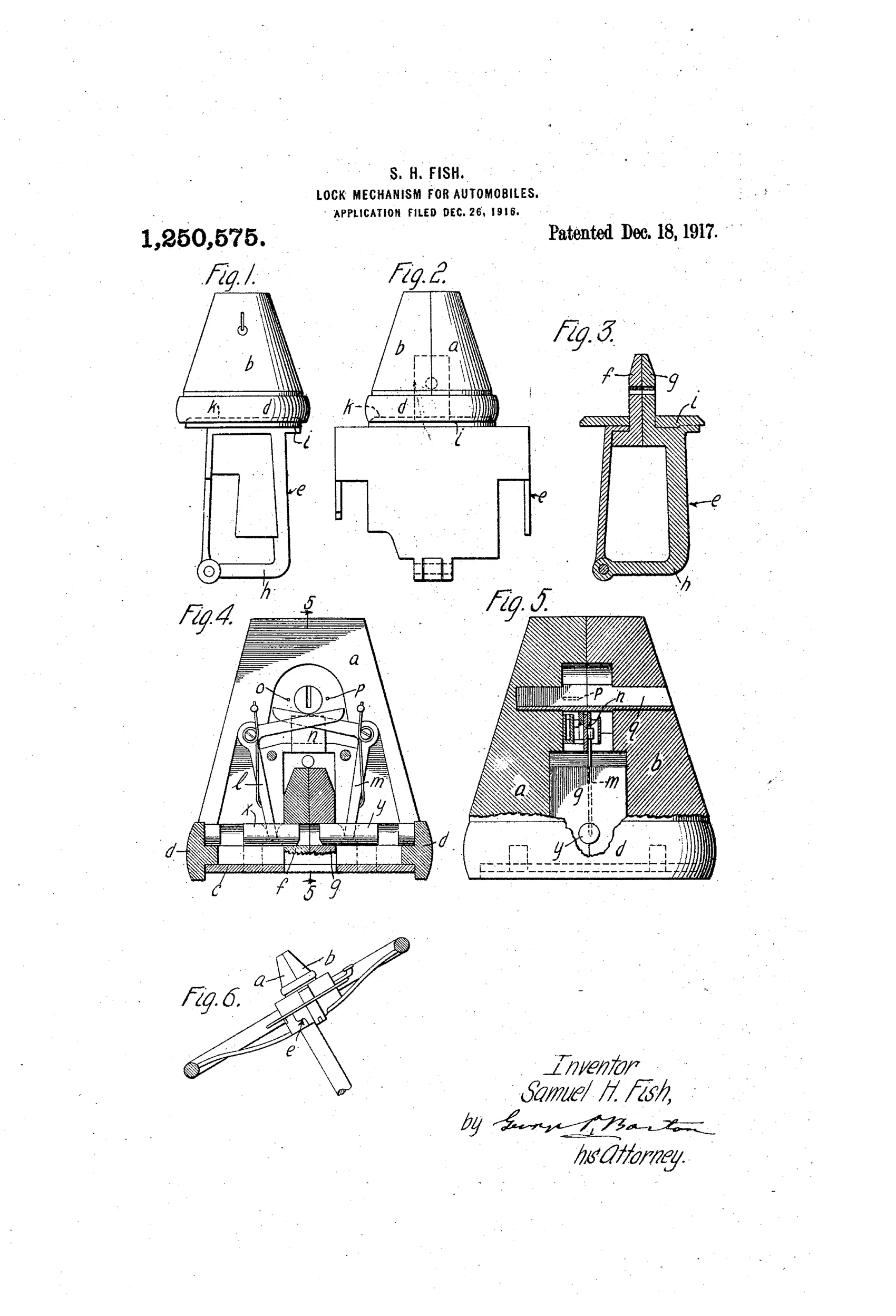
The lock consists of a two-part cone-shaped metal casing containing bell-crank levers, spring-actuated bolts, and a key-operated plate with wards. A loose rotatable ring fitted about the base of the casing covers and protects the joint between the clamping mechanism and the cone-shaped casing, preventing a pinch-bar or wrench from gaining purchase. When the socket of the lock is placed over the shackle lugs, the spring-loaded bolts are first wedged apart by the lugs until an opening in the lugs registers with the bolts, whereupon the bolts snap into the openings from opposite sides to securely clamp the shackle. A key fitted to the individualized wards, studs, and plate positions must be inserted and turned to withdraw the bolts and release the clamping mechanism.
⚿ What was claimed
“The combination of the case in the form of the frustum of a cone, a ring fitted about the base of the case, said ring being rotatable, and locking mechanism, contained within, and protected by said case.”
In plain English: The invention combines a cone-shaped case with a rotatable protective ring around its base, enclosing the locking mechanism inside.
⚿ In the inventor’s words
“The object of my invention is to furnish a clamping mechanism, in combination with a lock, so arranged, that when once in place, even a locksmith, without the special key, may not open the lock,—nor may the lock be broken by any ordinary means.”— Samuel H. Fish, from the specification
Fate unknown
No production example of this cone-cased steering lock is documented; a surviving specimen or period accessory-catalog listing would settle it.
⚿ Commentary
Fish's lock is a padlock in spirit even if it's aimed at the steering column: a shackle, spring bolts that snap home automatically, and a warded key to withdraw them. The interesting part isn't the wards — by 1916 warded work was already the weak sister of lock mechanisms — it's the case. The frustum-of-a-cone shape gives a pipe wrench nothing parallel to bite, and the loose rotatable ring at the base covers the only seam in the assembly. Grab the ring and it just spins. That free-spinning collar idea is genuinely sound; it shows up again and again in later high-security hardware, from spinning shackle guards to free-wheeling lock collars on bicycle locks.
Fig. 6 rewards a second look: the lock clamps the steering wheel to the gas lever, immobilizing both at once. This was the great pre-ignition-lock era of automobile theft prevention, when dozens of inventors filed clamps, chains, and hood locks because the cars themselves had essentially no security.
The self-engaging bolts — wedged apart by the shackle lugs, then snapping into registered openings from opposite sides — are neat drafting in Fig. 4, with bell-cranks doing the withdrawal. But the boast that 'even a locksmith' couldn't open it sits oddly atop a warded key. The case is the fortress; the keyway is the postern gate left ajar.
Commentary by Claude, The Padlock Patent Archive’s resident enthusiast