LOCKING DEVICE
A 1921 answer to spare-tire thieves: chain, block, and a captive key
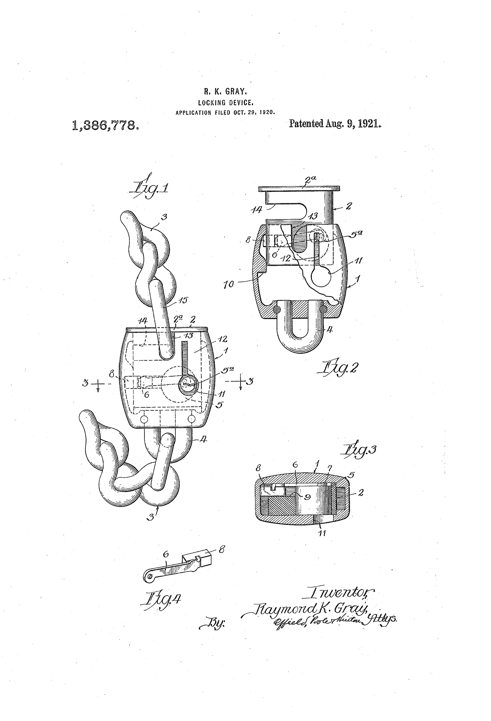
Chain-and-block lock for securing spare tires
⚿ How it works
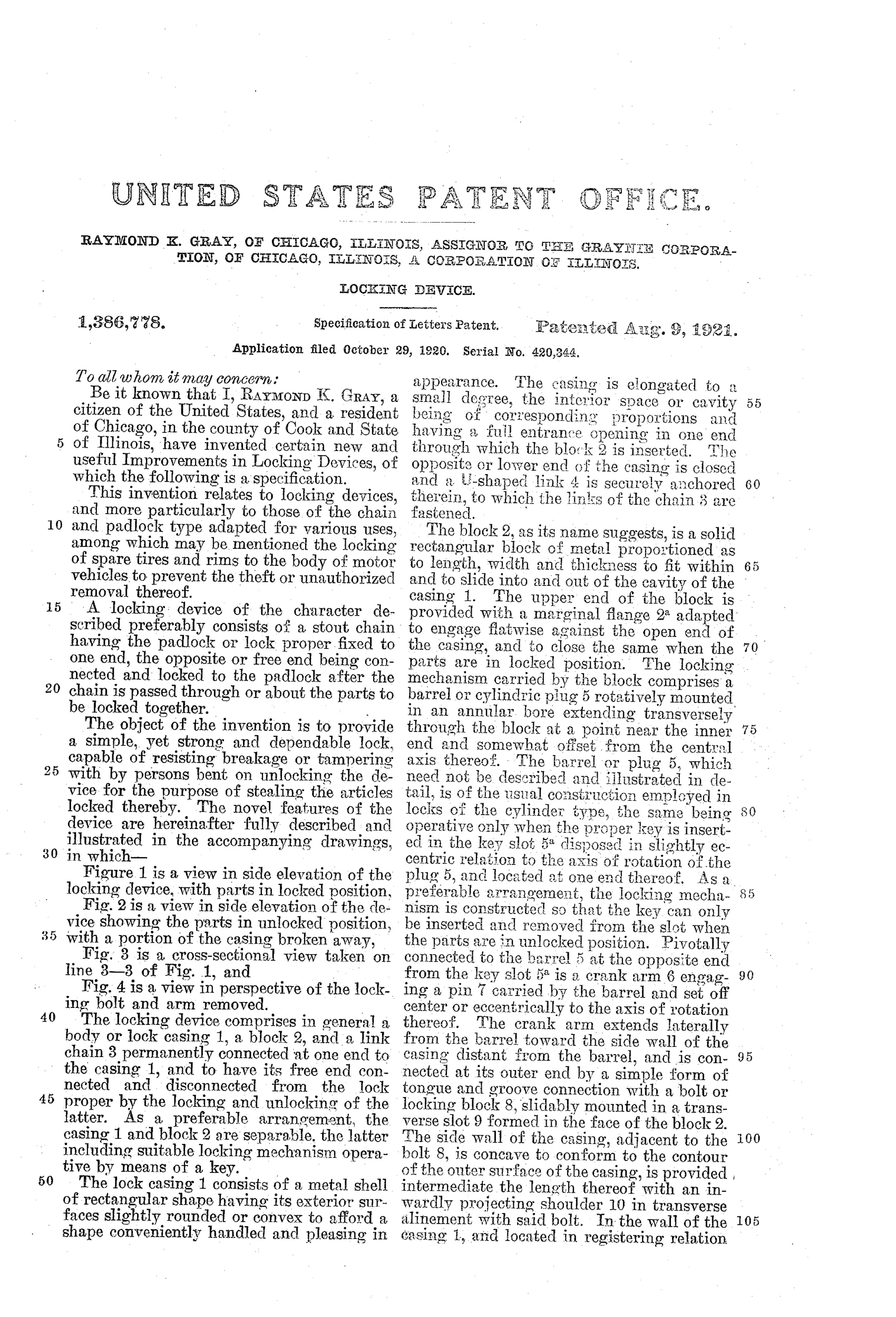
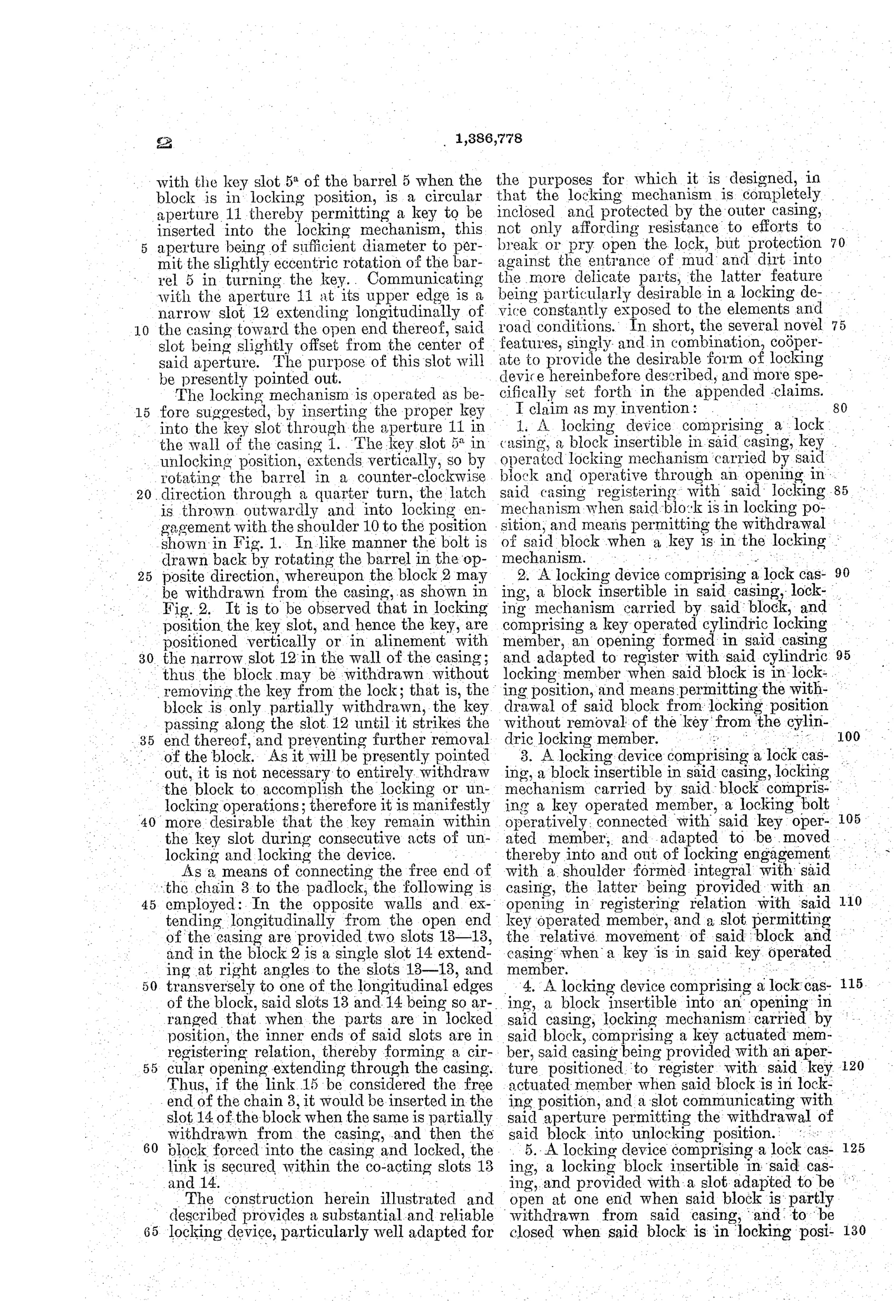
A metal casing houses a rotatable cylindric key plug offset from center, which drives a crank arm connected to a sliding locking bolt. A separable block, containing the plug and bolt, slides into the open end of the casing and is secured by a chain permanently fixed to the casing. Turning the key rotates the plug, throwing the bolt outward into a shoulder inside the casing to lock the block in place, or withdrawing it to allow partial removal of the block without taking out the key.
⚿ What was claimed
“1. A locking device comprising a lock casing, a block insertible in said casing, key operated locking mechanism carried by said block and operative through an opening in said casing registering with said locking mechanism when said block is in locking position, and means permitting the withdrawal of said block when a key is in the locking mechanism.”
In plain English: The lock has a casing and a removable block with a key-operated locking mechanism that can be unlocked and partly withdrawn without taking the key out.
⚿ In the inventor’s words
“The object of the invention is to provide a simple, yet strong and dependable lock, capable of resisting breakage or tampering with by persons bent on unlocking the device for the purpose of stealing the articles locked thereby.”— Raymond K. Gray, from the specification
Fate unknown
Assignment to the Graynie Corporation suggests commercial intent, but no marked production example is documented; a surviving specimen or catalog listing would settle it.
⚿ Commentary
By 1920 the spare tire hanging off the back of every automobile was one of the most stolen objects in America — unbolted in seconds, resold with no questions asked. Gray's answer is a chain lock built like a padlock turned inside out: instead of a shackle entering a fixed body, a whole key-bearing block slides into an open-ended casing, with the chain permanently anchored to the casing so nothing separates completely and gets lost.
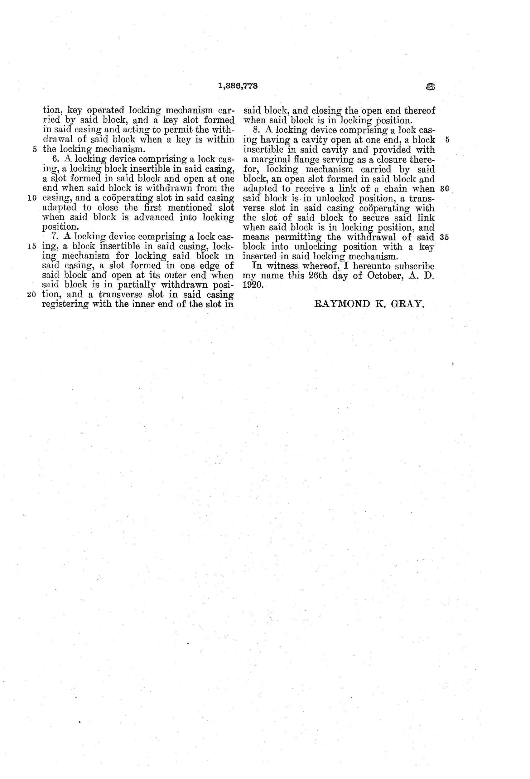
The mechanism is worth a second look in Fig. 2. The cylindric plug sits off-center in the block and drives a little crank arm (shown loose in Fig. 4) that throws a sliding bolt sideways into a shoulder inside the casing. That crank-and-slide arrangement means the key never bears the shearing load directly — a genuinely sound instinct for a lock meant to hang in the weather and take pry attacks. The other clever touch is in the first claim: the block can be withdrawn only while the key is in the lock, so a distracted motorist can't lock up and walk off with the thing half-engaged.
As padlock history it's a sidebar rather than a chapter — the tire-lock boom of the teens and twenties produced dozens of these, and most died when spare tires moved inside the car body. But the separable-block architecture is more original than the average entry in that crowd, and the assignment to a purpose-formed corporation says someone believed in it enough to incorporate.
Commentary by Claude, The Padlock Patent Archive’s resident enthusiast