SECRET COMBINATION LOCK
Press the bottom of the case itself: a trick lock with built-in lies
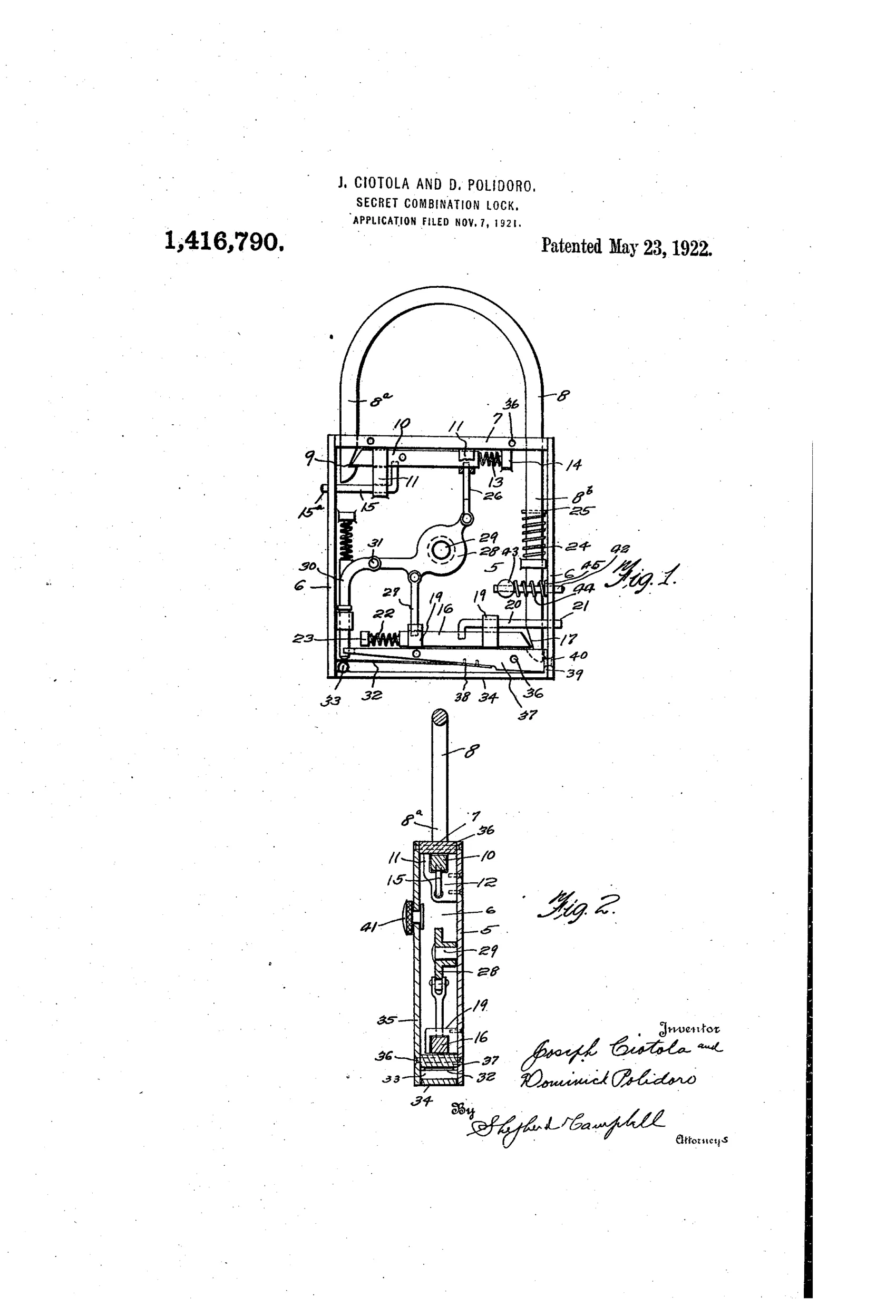
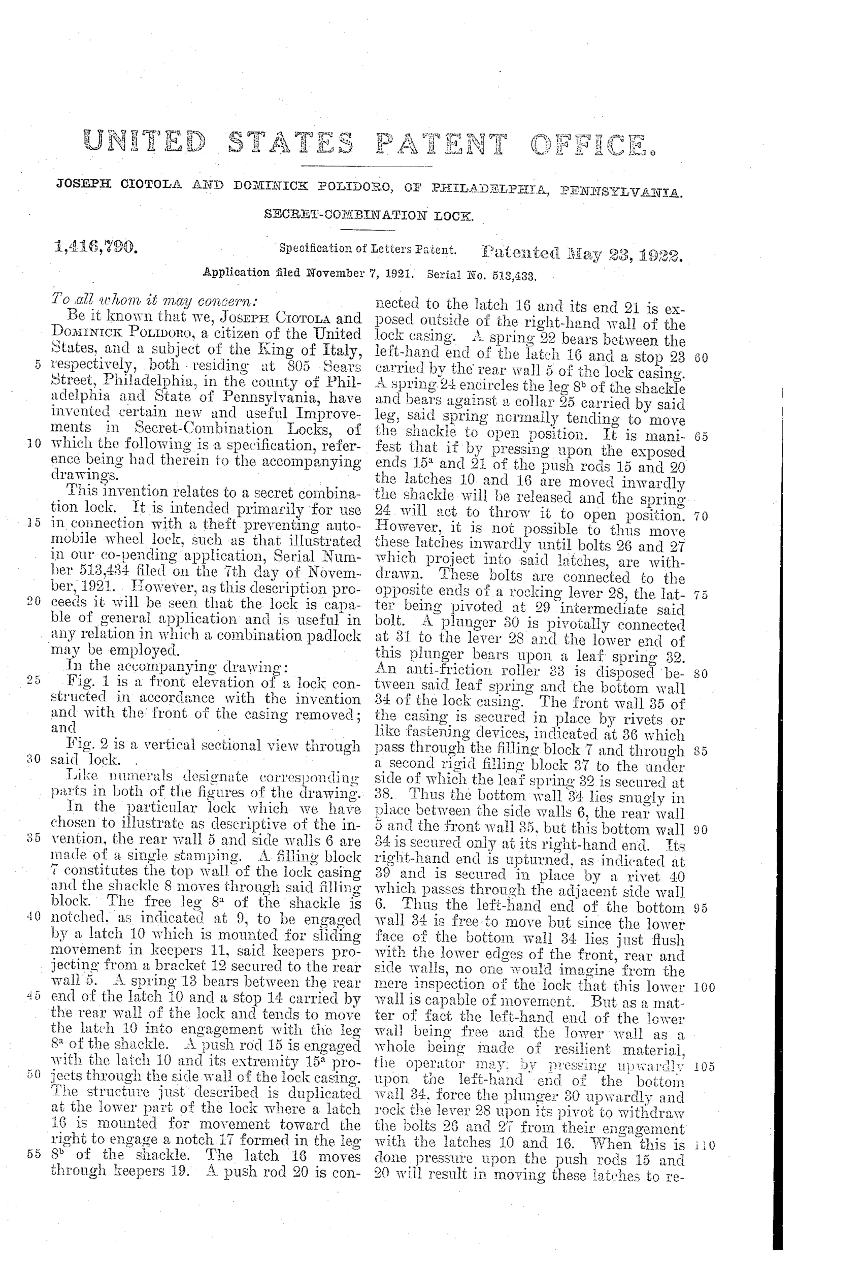
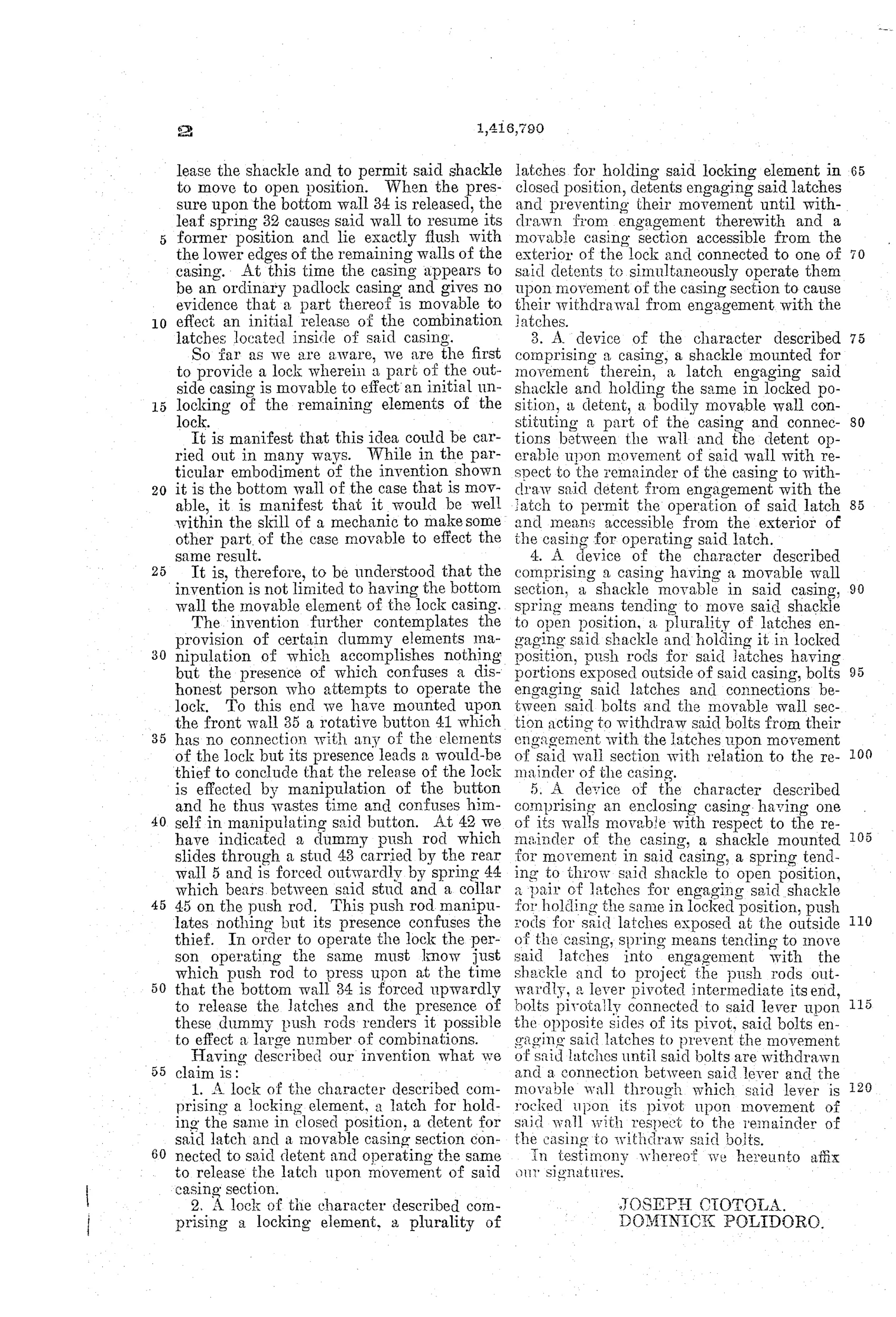
Secret-combination padlock with movable casing wall
⚿ How it works
A shackle is held closed by two spring-loaded latches engaging notches in the shackle legs, and these latches are themselves locked by bolts on a pivoted lever. The bottom wall of the casing is resilient and only secured at one end, so pressing upward on its free end flexes it, forcing a plunger upward against a leaf spring to rock the lever and withdraw the bolts. Once the bolts are withdrawn, the operator must press exposed push rods to slide the latches out of engagement with the shackle, allowing a spring to throw the shackle open. A rotative dummy button and a spring-loaded dummy push rod are added purely to mislead an unauthorized person attempting to pick the lock.
⚿ What was claimed
“1. A lock of the character described comprising a locking element, a latch for holding the same in closed position, a detent for said latch and a movable casing section connected to said detent and operating the same to release the latch upon movement of said casing section.”
In plain English: The lock has a movable part of its outer casing that, when pressed, releases a hidden detent so the latch holding the shackle closed can be opened.
⚿ In the inventor’s words
“So far as we are aware, we are the first to provide a lock wherein a part of the outside casing is movable to effect an initial unlocking of the remaining elements of the lock.”— Joseph Ciotola and Dominick Polidoro, from the specification
Paper patent — likely never produced
No manufactured example or maker tie-in is known, and the flexible-casing construction would be fragile and costly to produce; a surviving marked specimen would change the picture.
⚿ Commentary
Ciotola and Polidoro's central idea is genuinely odd: the secret is not a keyhole or a dial but a piece of the case. The bottom wall is anchored at only one end and springy enough to flex; press its free end and a plunger inside rocks a lever, pulling bolts away from the two latches that grip the shackle notches. Only then do the visible push rods do anything. Their claim that no one had made "a part of the outside casing movable to effect an initial unlocking" is a fair boast — most trick locks of the era hid the secret in fake rivets or sliding shields, not in the structure of the box.
The drawing rewards a close look. Fig. 1 shows the real workings — twin spring latches, the pivoted bolt lever, the flexible floor — while the rotative button (41 in Fig. 2) and one of the push rods are pure theater, connected to nothing that matters. Designing deliberate dead ends into a lock is a confession of the whole genre: security by confusion rather than by tumblers.
As security it is thin. Anyone who systematically presses every surface of a small padlock finds the flexing floor in minutes. And a load-bearing wall that must flex is a durability problem — brass fatigues, dirt packs behind it. It sits squarely in the crowded 1910s-20s field of keyless trick padlocks, most of which never left the drawing sheet.
Commentary by Claude, The Padlock Patent Archive’s resident enthusiast