AUTOMATIC SAFETY LOCK DEVICE.
A snap-shut chain lock for the tire-theft epidemic, with a faucet afterthought
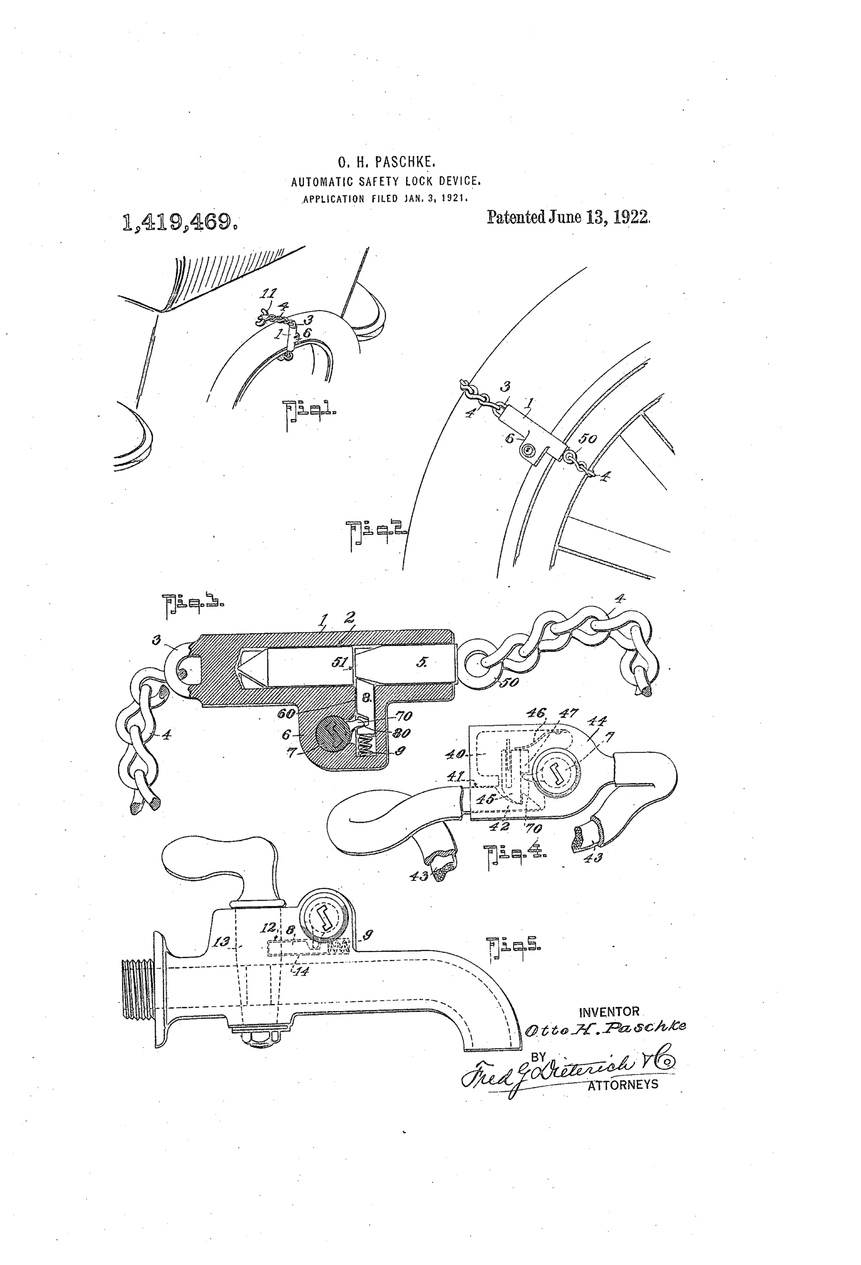
Automatic anti-theft chain lock for wheels/tires
⚿ How it works
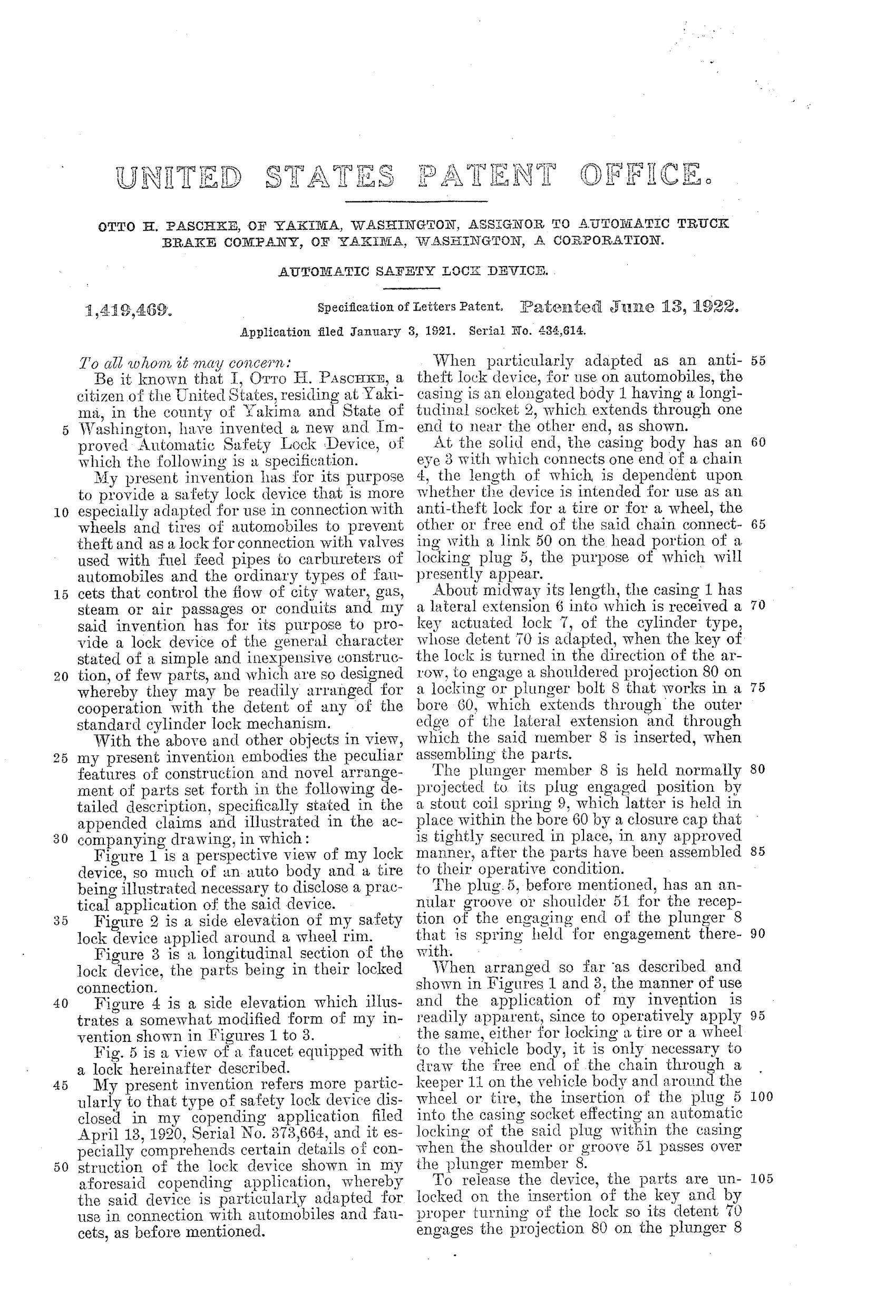
A casing has a longitudinal socket that receives a locking plug attached to a chain looped around a wheel or tire and secured to the vehicle body. A spring-loaded plunger bolt, mounted at right angles to the socket, automatically snaps into an annular groove on the plug as it is inserted, locking it in place. A key-actuated cylinder lock with a detent engages a shouldered projection on the plunger bolt so that turning the key withdraws the bolt against its spring, releasing the plug. A modified version replaces the plug and bore with a chambered casing, a hook member, and a flexible leather-covered cable for connecting to wheels or tires, and the same mechanism can be adapted to lock a faucet valve.
⚿ What was claimed
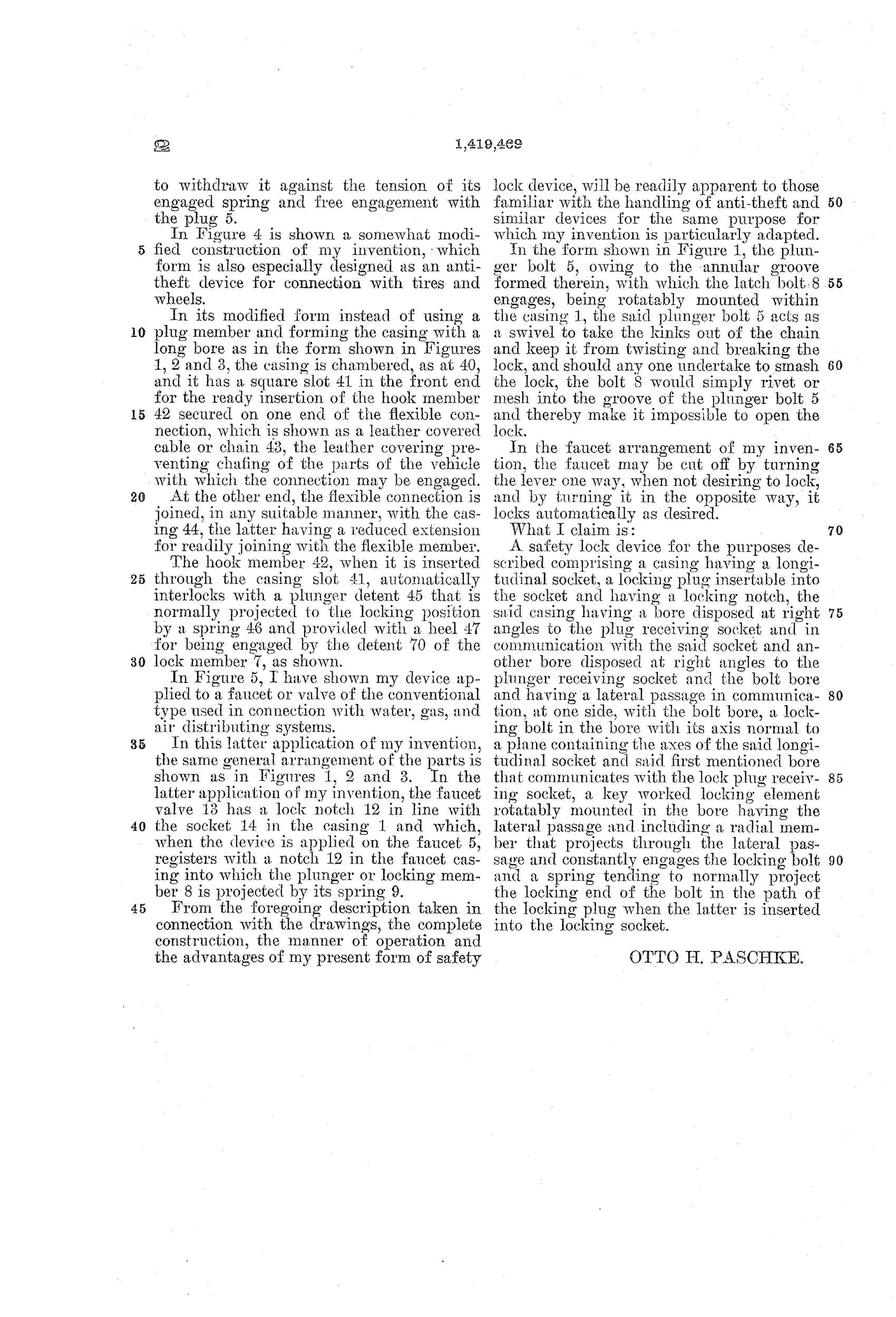
“A safety lock device for the purposes described comprising a casing having a longitudinal socket, a locking plug insertable into the socket and having a locking notch, the said casing having a bore disposed at right angles to the plug receiving socket and in communication with the said socket and another bore disposed at right angles to the plunger receiving socket and the bolt bore and having a lateral passage in communication, at one side, with the bolt bore, a locking bolt in the bore with its axis normal to a plane containing the axes of the said longitudinal socket and said first mentioned bore that communicates with the lock plug receiving socket, a key worked locking element rotatably mounted in the bore having the lateral passage and including a radial member that projects through the lateral passage and constantly engages the locking bolt and a spring tending to normally project the locking end of the bolt in the path of the locking plug when the latter is inserted into the locking socket.”
In plain English: The lock consists of a casing with a socket for a locking plug and a spring-loaded bolt that automatically catches a notch in the plug when inserted, with a key-turned cylinder mechanism that must be operated to withdraw the bolt and release the plug.
⚿ In the inventor’s words
“should any one undertake to smash the lock, the bolt 8 would simply rivet or mesh into the groove of the plunger bolt 5 and thereby make it impossible to open the lock.”— Otto H. Paschke, from the specification
Fate unknown
No production example from the Automatic Truck Brake Company is documented; a marked chain-and-plug specimen would settle it.
⚿ Commentary
Paschke's device answers a real 1921 problem: tires were expensive, easily unbolted, and among the most-stolen items in early motoring. His solution is a chain looped through the wheel and anchored to the body, closed by a plug that snaps into a casing — no key needed to lock, only to unlock. That spring-loaded convenience is the whole pitch. The mechanism is a plunger bolt sitting at right angles to the plug socket, riding into an annular groove as the plug seats, with a key-turned cylinder whose radial detent hauls the bolt back against its spring.
The best line in the specification is pure inventor's bravado: smash the lock, he says, and the bolt 'would simply rivet or mesh into the groove' and jam shut forever. That's optimistic — deforming a spring bolt into its own groove is not a defense so much as a coin flip — but it shows he was thinking about attack, not just operation.
Fig. 5 is the tell. Having built a general-purpose snap latch, Paschke bolts it onto a faucet handle, presumably to stop pilferage of water or beer. That kind of scope creep is common in single-patent inventors and rare in lock companies. Assigned to the Automatic Truck Brake Company of Yakima — not a lock maker — this sits in the crowded 1915-1925 wave of automobile anti-theft padlocks, most of which the established padlock houses eventually served better and cheaper.
Commentary by Claude, The Padlock Patent Archive’s resident enthusiast