TIRE CHAIN LOCK
Every surface spins free: a tire lock designed to defeat the wrench
Anti-theft chain lock for spare tires
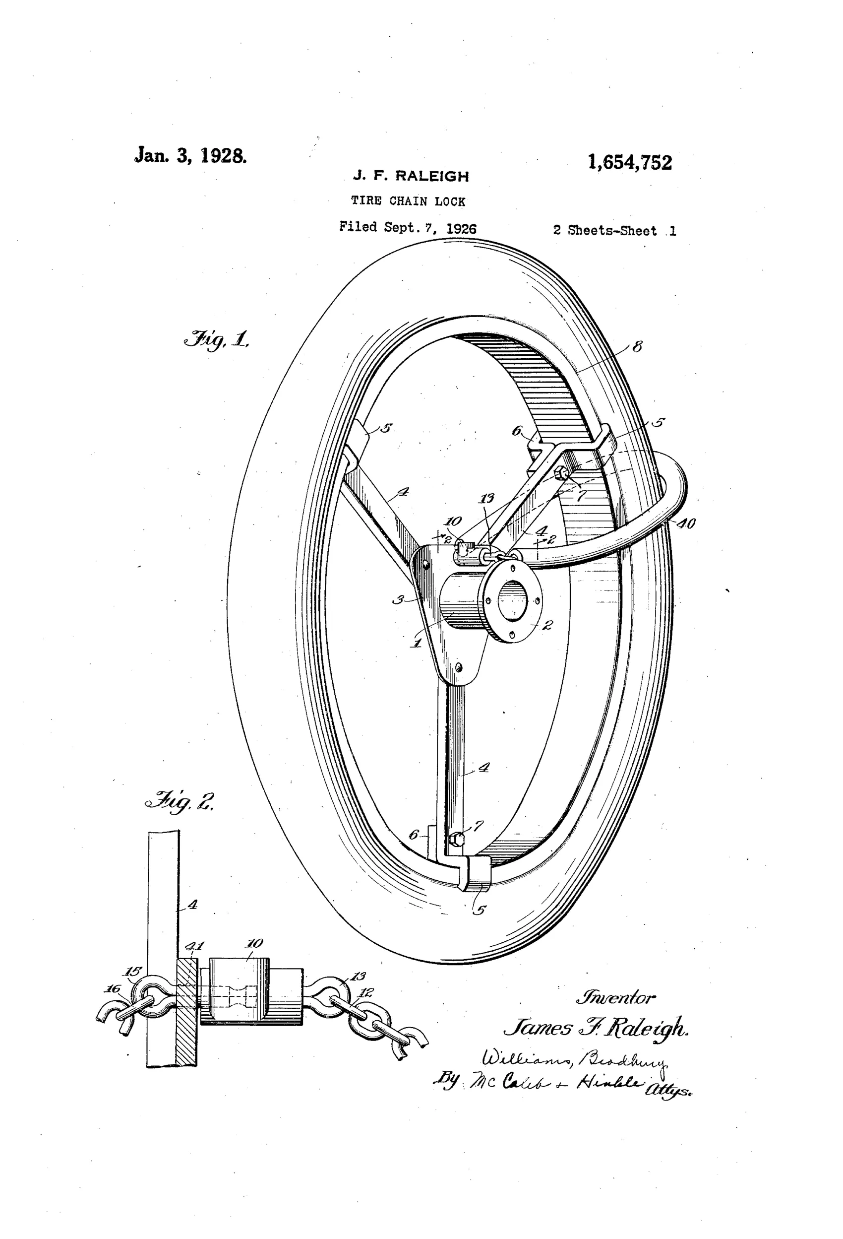
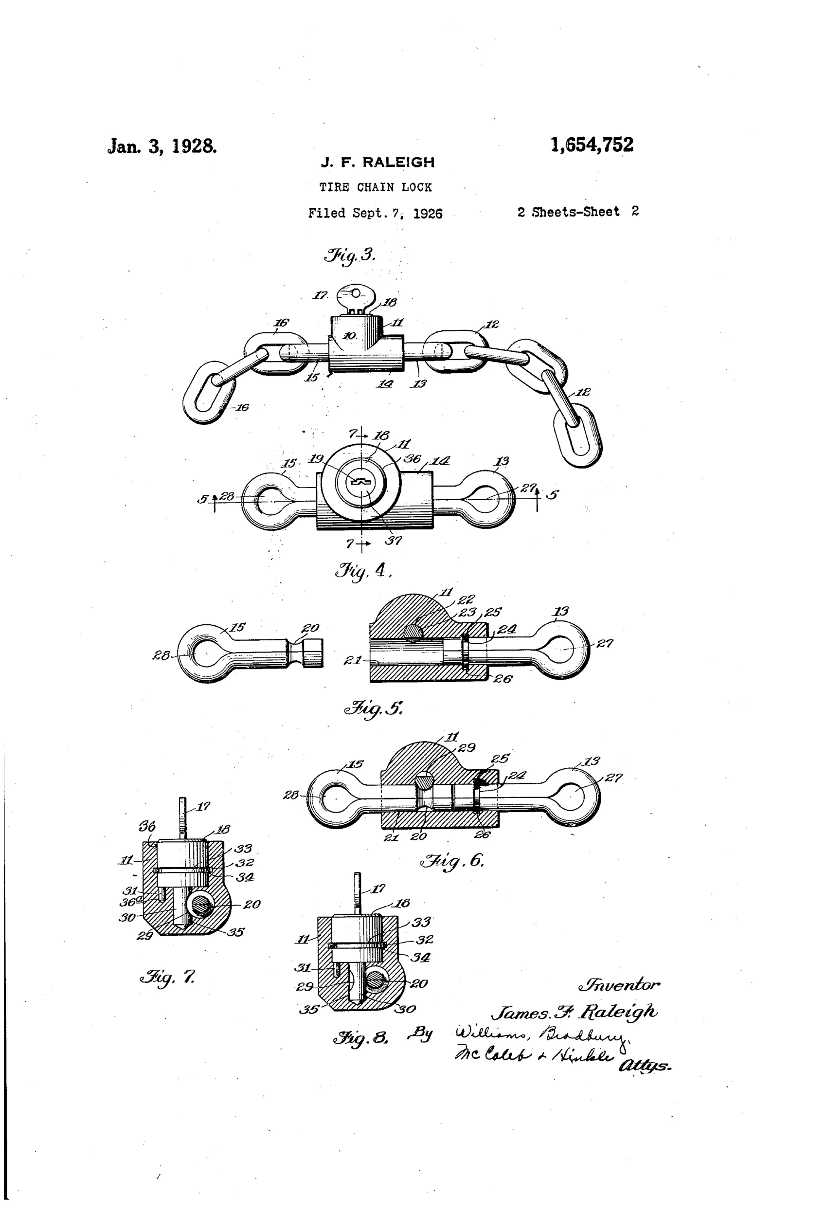
⚿ How it works
A flexible chain is looped through the wheel spider and rim so that the wheel cannot be removed without breaking it. The chain's ends terminate in cotter-pin-shaped eyebolts held inside a small elongated lock casing. A key-actuated rotatable locking bolt engages an annular slot on one eyebolt while a split steel spring ring rotatably retains the other eyebolt and the lock barrel itself, so every exposed surface is free to spin relative to the others. Because no fixed pins or flats are exposed, a wrench cannot grip and twist any part to break the lock apart.
⚿ What was claimed
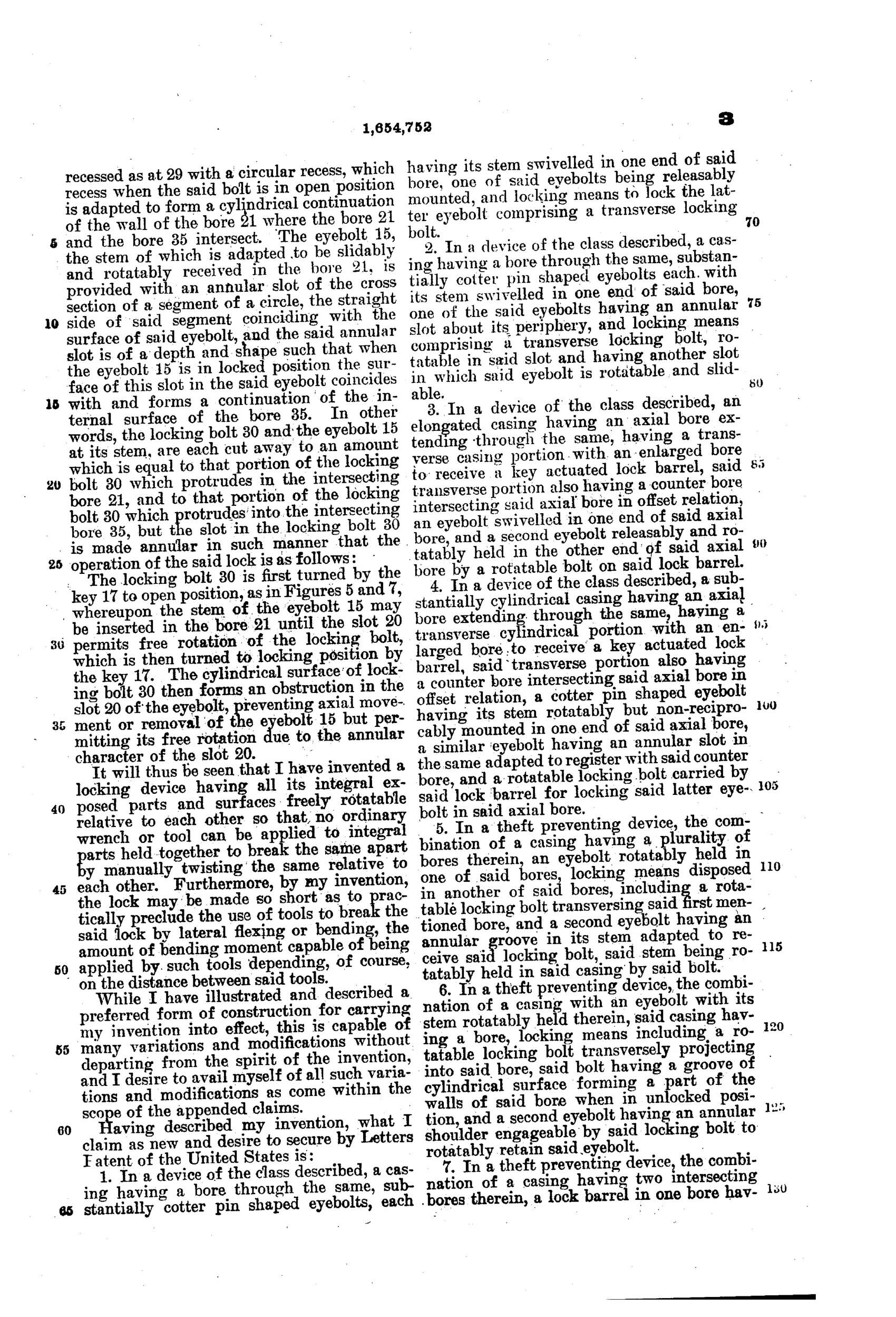
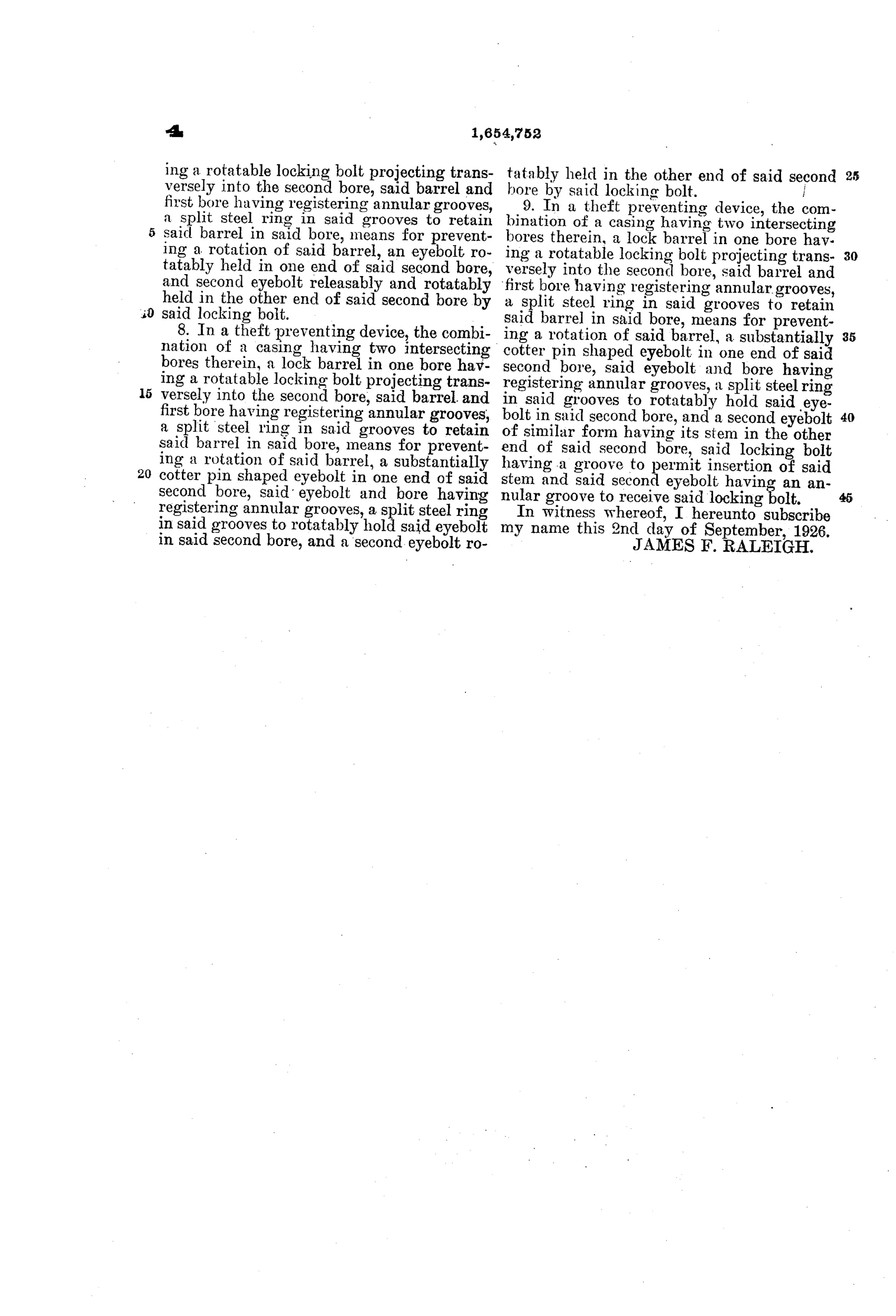
“In a device of the class described, a casing having a bore through the same, substantially cotter pin shaped eyebolts, each having its stem swivelled in one end of said bore, one of said eyebolts being releasably mounted, and locking means to lock the latter eyebolt comprising a transverse locking bolt.”
In plain English: The lock has a casing with a bore holding two cotter-pin-shaped eyebolts that can each spin freely in place, one of which can be released and relocked by a sideways-turning locking bolt.
⚿ In the inventor’s words
“Other locks are easily broken by fracturing their brittle cast-iron casing with a sharp hammer blow, but my invention overcomes all these disadvantages and others.”— James F. Raleigh, from the specification
Fate unknown
Pines Winterfront was an active accessory manufacturer, which makes production plausible, but no marked specimen or catalog listing is documented; either would settle it.
⚿ Commentary
By the mid-1920s the spare tire hanging off the back of a Ford was one of the most stolen items in America, and a small industry sprang up around locking it down. Raleigh's entry is a chain lock, but the interesting part isn't the chain — it's the little cylindrical casing at the end of it, and the single idea that organizes the whole design: nothing on the outside is fixed.
Look at Fig. 2 on this sheet. The two cotter-pin-shaped eyebolts that anchor the chain each swivel in the bore, one retained by a split steel spring ring, the other by the key-turned transverse bolt, and the barrel itself rotates in its housing. A thief with a pipe wrench gets nothing to react against; whatever he grips just turns. It's the same insight that later gave us free-spinning collars on bicycle U-locks and hardened spinning sleeves on hasps, applied here with 1926 hardware. Raleigh's own dig at competitors — that their brittle cast-iron cases shatter under a hammer blow — tells you exactly what the market's weak point was.
As padlock engineering it's modest: the key mechanism is a simple rotating bolt engaging an annular groove, nothing a lever-tumbler man would admire. But as security thinking it's sound, and the assignment to Pines Winterfront — a real Chicago auto-accessory maker — suggests this was drawn with a production line in mind, not just a patent certificate for the wall.
Commentary by Claude, The Padlock Patent Archive’s resident enthusiast