LOCK MECHANISM
A toggle-tightened, hardened chain lock for the era of stolen spare tires
Chain lock and tightener for spare tires
⚿ How it works
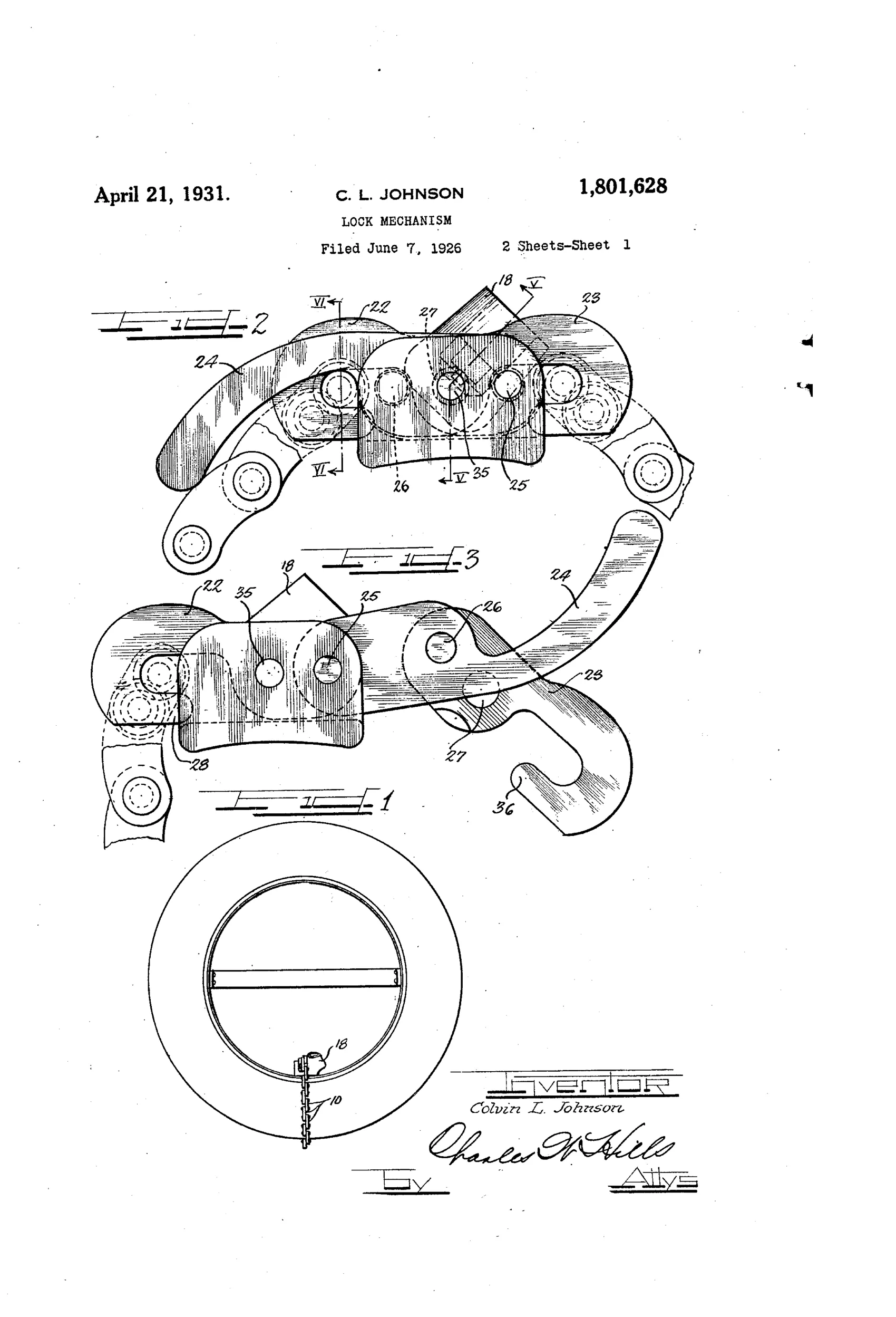
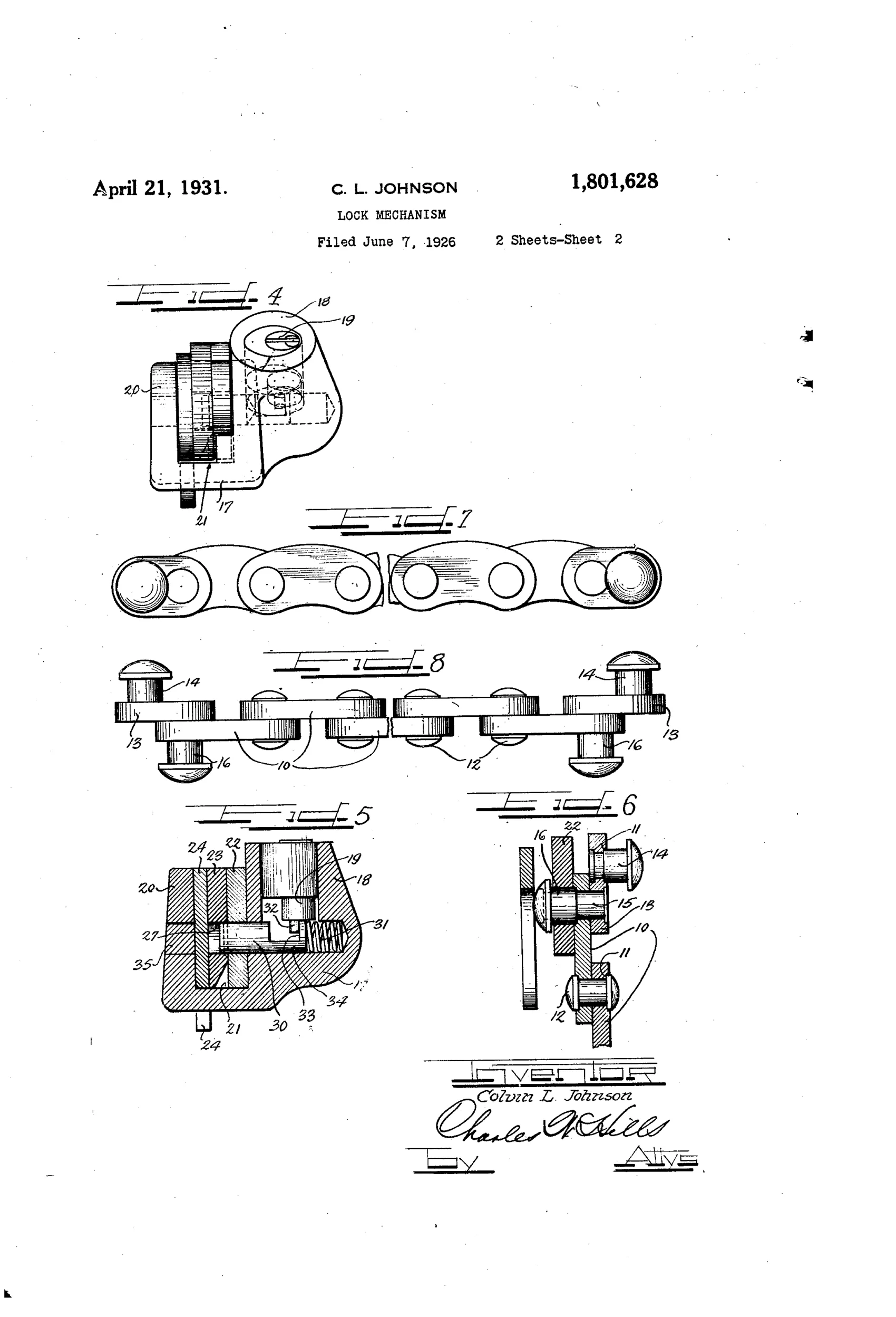
A chain built of curved links with counterbored shoulders and headed studs is engaged at one end by a chain hook that is semi-permanently locked to a body. A pivoted tightening lever (toggle) draws a second chain hook down over a spring-loaded sliding bolt operated by an eccentric pin on a cylinder lock. The bolt snaps into an aperture in the hook to secure it, taking up slack and preventing rattling, and a key-operated cylinder lock retracts the bolt to release the hook. The links and rivets are hardened and cadmium plated to resist cutting, filing, drilling or sawing.
⚿ What was claimed
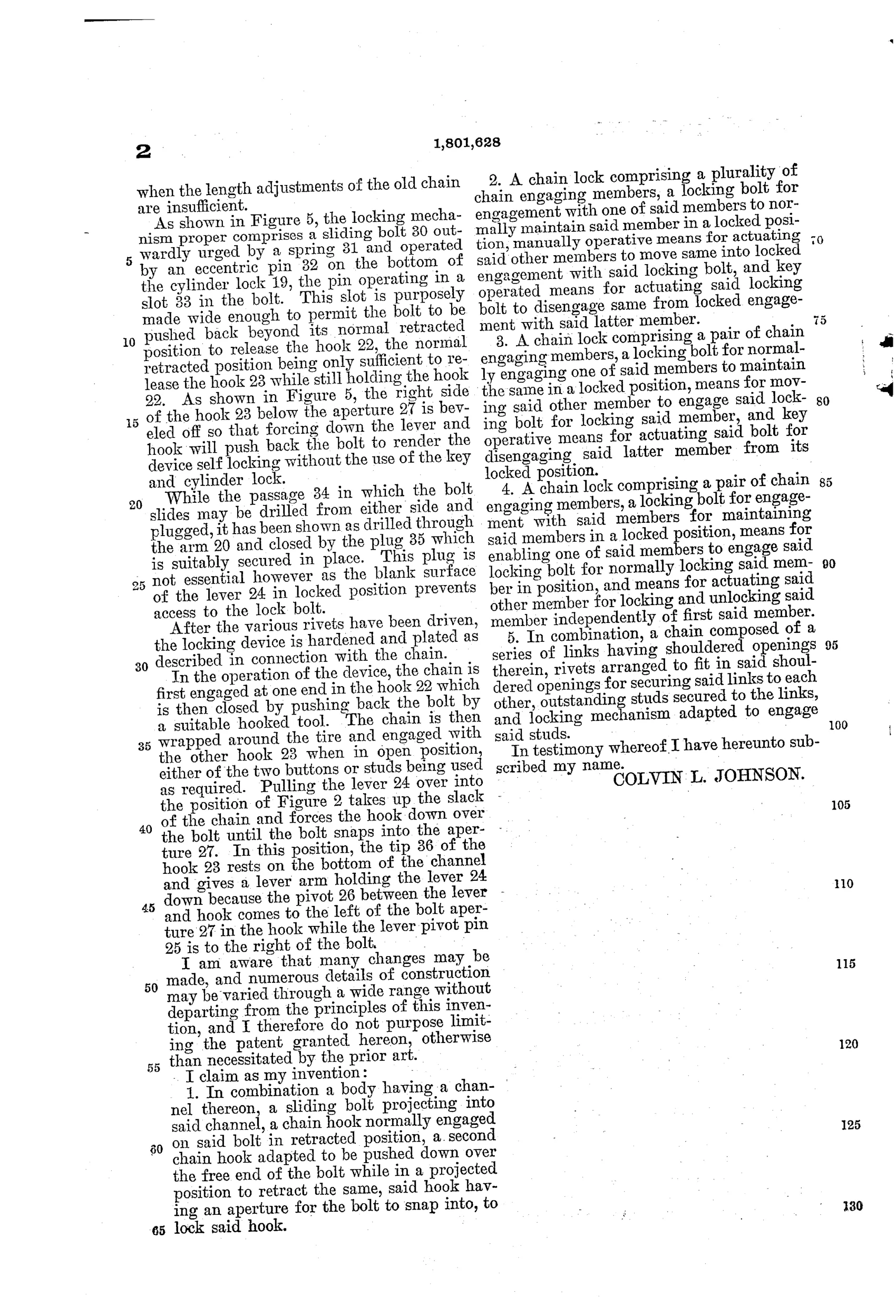
“In combination a body having a channel thereon, a sliding bolt projecting into said channel, a chain hook normally engaged on said bolt in retracted position, a second chain hook adapted to be pushed down over the free end of the bolt while in a projected position to retract the same, said hook having an aperture for the bolt to snap into, to lock said hook.”
In plain English: A lock body has a spring bolt in a channel; one chain hook stays engaged on the retracted bolt while a second hook is pushed down over the bolt to push it back and then snap into a hole in that hook, locking it in place.
⚿ In the inventor’s words
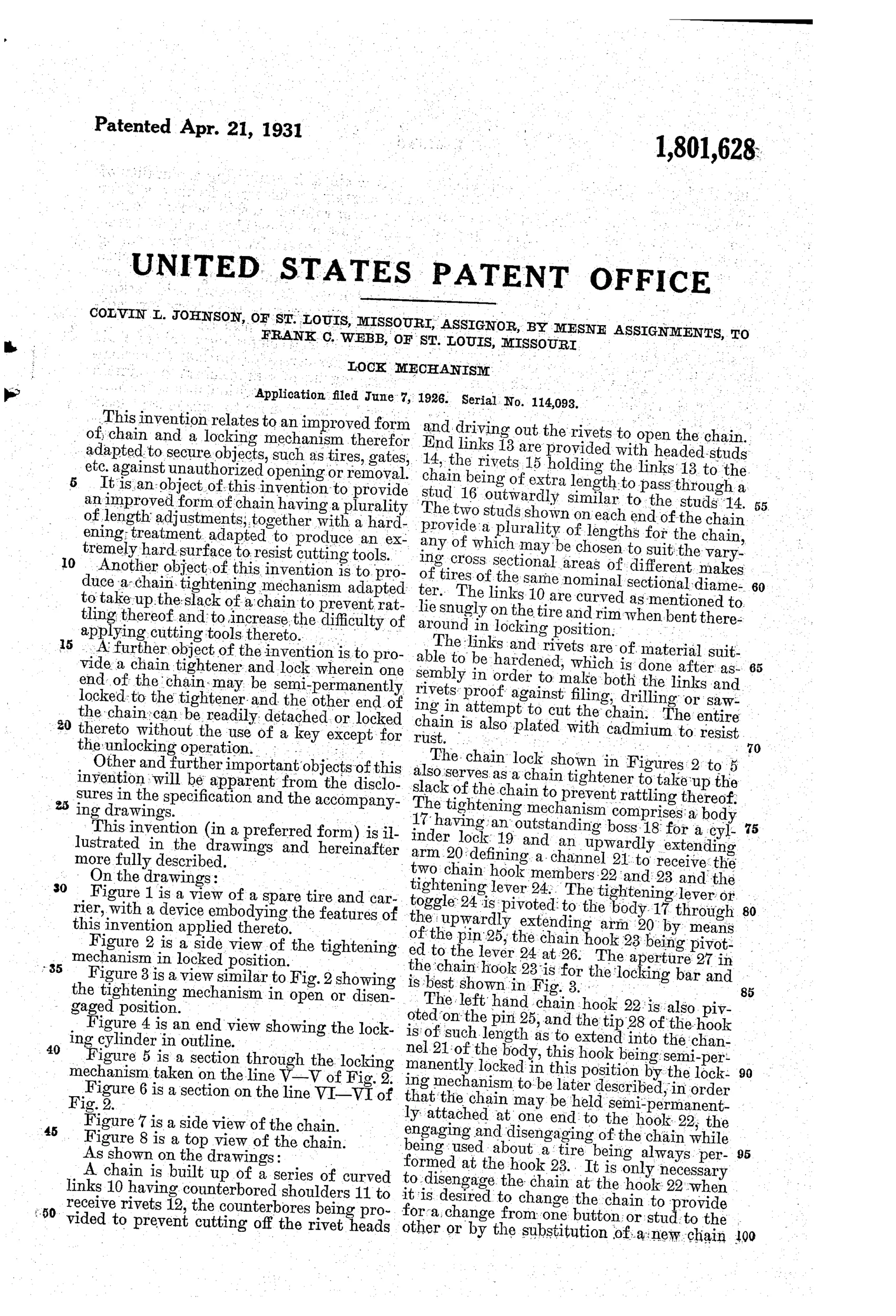
“The links and rivets are of material suitable to be hardened, which is done after assembly in order to make both the links and rivets proof against filing, drilling or sawing in attempt to cut the chain.”— Colvin L. Johnson, from the specification
Fate unknown
Tire chain locks were a real 1920s accessory market, but I know of no documented example of this specific toggle-and-bolt design; a marked specimen or Webb-branded catalog listing would settle it.
⚿ Commentary
This one earns its place at the edge of the padlock category: it's really a purpose-built chain lock for spare tires, filed in 1926 when a mounted spare on a rear carrier was among the most stealable items on an automobile. Johnson's answer is a system, not just a lock — a chain of curved, riveted links hardened after assembly (so no soft spots at the joints), a toggle lever that pulls the chain tight against the tire to stop rattling, and a spring bolt operated by a modern cylinder lock rather than a lever or ward key.
The claim's cleverest detail is easy to miss in the drawing: the same sliding bolt does double duty. One chain hook lives semi-permanently on the bolt in its retracted position, while the second hook is slammed down over the projected bolt, camming it back until it snaps into an aperture in the hook. That means locking up requires no key at all — push the hook home and it self-latches — while release goes through the cylinder. That slam-shut convenience is exactly the padlock logic of the period applied to a vehicle accessory.
Figures 7 and 8 reward a close look too: the links are shouldered and counterbored so the studs sit flush, denying a hacksaw or bolt cutter a clean purchase. Whether the toggle tightener survived real-world mud and corrosion is another question, but the anti-theft thinking is genuinely thorough for 1926.
Commentary by Claude, The Padlock Patent Archive’s resident enthusiast