IMPROVEMENT IN COMBINATION-PADLOCKS.
No shackle at all — the bolt bites straight between chain links
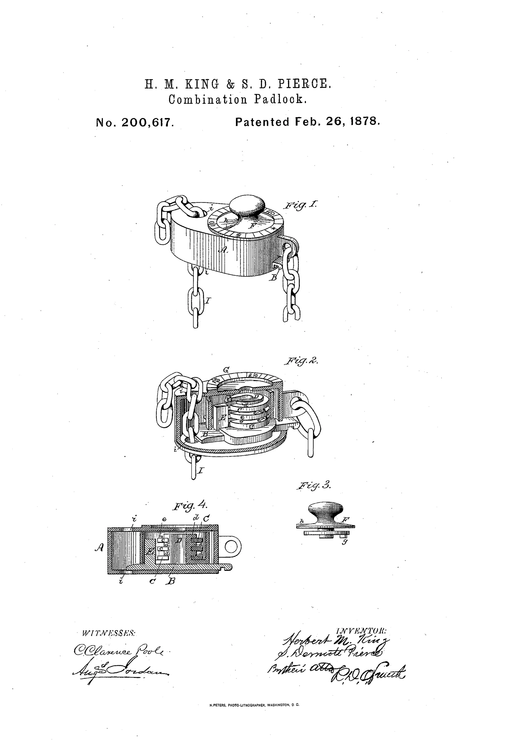
Chain-locking combination padlock with rotating permutation rings
⚿ How it works
The lock's bolt B slides flatwise across an orifice i in case A, entering between two links of a chain and jamming the intermediate link against the edge of the orifice to prevent withdrawal. A stud E on the bolt engages a series of permutation rings C mounted on a hollow center post D, each ring having a notch and a pin e that can engage the pin of the adjacent ring. Rotating the index-plate F (via a knob and dial G with pointer h) turns the rings in sequence through a set combination of motions until all ring openings align, allowing the stud E to retreat into the hollow hub D and the bolt to be withdrawn.
⚿ What was claimed
“1. A case, A, with an orifice, i, adapted to receive a chain, combined with the locking-bolt B, moving flatwise across said orifice to engage between the links of a chain in the manner shown, and the combination locking-rings C C, substantially as set forth.”
In plain English: The lock consists of a case with a hole for a chain, a bolt that slides across the hole to grip the chain links, and a set of rotating combination rings that hold the bolt locked.
⚿ In the inventor’s words
“The positions of the pins e may be varied, and the combination movements may thereby be changed or varied indefinitely.”— Herbert M. King and S. Dermott Pierce, from the specification
Fate unknown
No manufactured example of this chain-clamping design is documented; a surviving marked specimen would settle it.
⚿ Commentary
Most combination padlock patents of the 1870s fuss over the ring mechanism and take the shackle for granted. King and Pierce did the opposite: they threw the shackle away. Their case has a hole bored through it, you thread a chain through, and a flat bolt slides across the orifice to trap an intermediate link against the edge. The lock becomes a clamp on the chain itself, which is why Fig. 1 shows chains sprouting from three directions — the thing works anywhere along the chain's length, not just at a hasp.
The combination side is a pin-transfer mechanism that dial-safe collectors will recognize instantly: rings on a hollow post, each carrying a pin that picks up the next ring after nearly a full turn. Turn the top knob back and forth through the sequence, the notches line up, the stud on the bolt drops into the hollow hub, and the bolt retreats. Fig. 2's cutaway shows the ring stack clearly. It's essentially a safe-dial wheel pack shrunk into a padlock two decades before that became common practice.
The weak point is obvious in Fig. 4: the whole security of the grip depends on one link jammed against a case edge. A hard pull on the chain loads the bolt in shear at a single point. Clever packaging, honest single-dial operation — but I know of no production example, and keyless permutation patents from small partnerships usually stayed on paper.
Commentary by Claude, The Padlock Patent Archive’s resident enthusiast