Flexible Key for Locks.
A key that bends: coiled-wire shank threads a serpentine keyway
A flexible coiled-wire key for locks
⚿ How it works
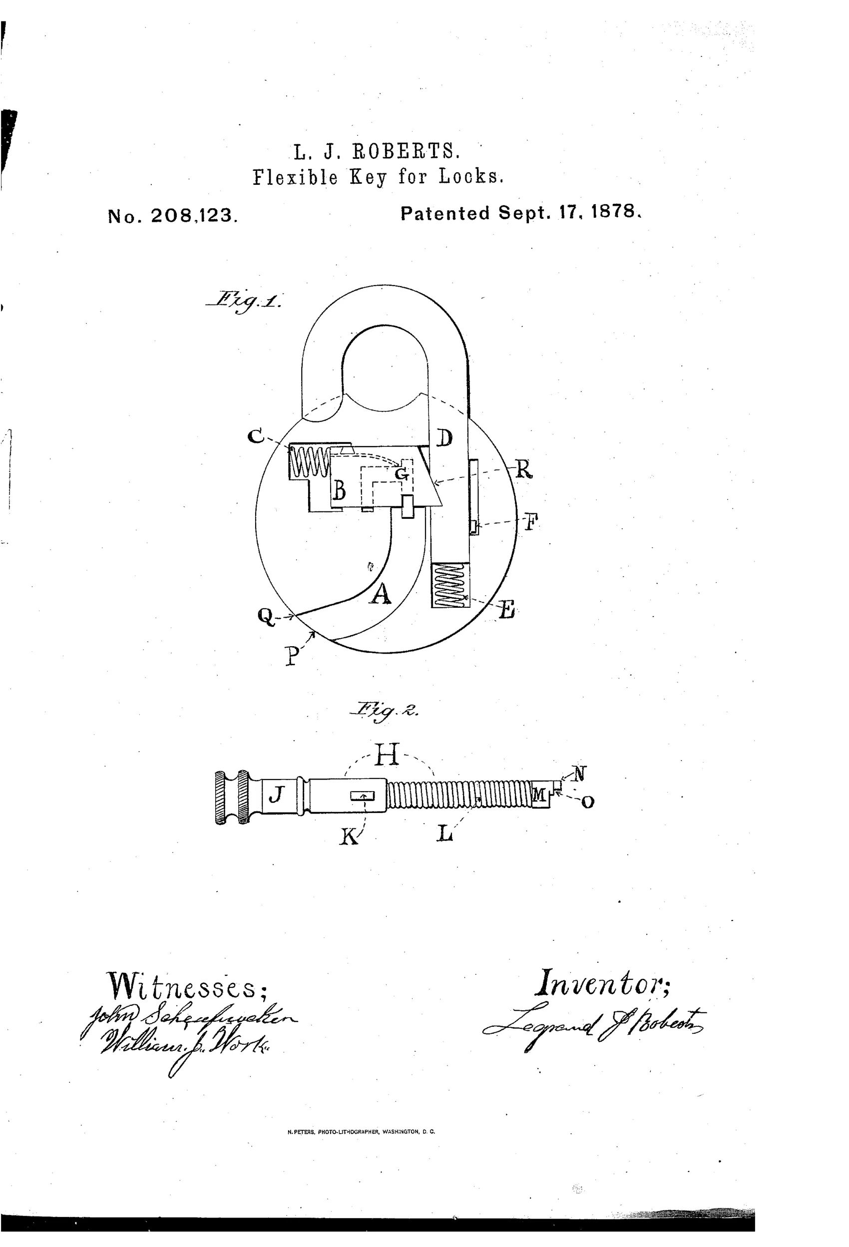
The lock has a curved or serpentine passage leading from its exterior to the guards of the bolt. The key's shank is formed of coiled wire, making it flexible so it can bend to follow this curved passage. As the key is pushed in and turned, projections and indentations on its head engage the bolt's guards, sliding the spring-loaded bolt out of a staple to release the lock. A staple spring and stop regulate the staple's movement so the lock can be refastened by pressing the staple down.
⚿ What was claimed
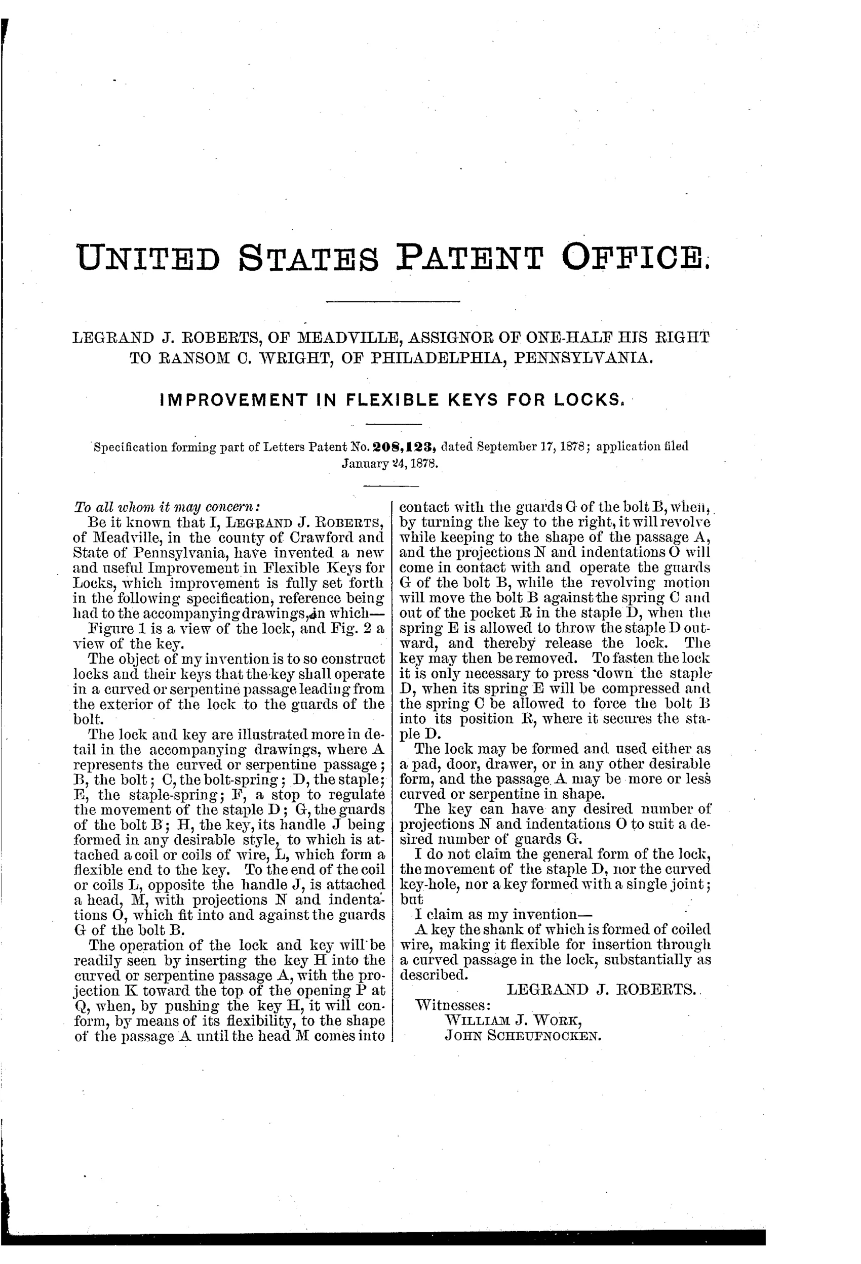
“A key the shank of which is formed of coiled wire, making it flexible for insertion through a curved passage in the lock, substantially as described.”
In plain English: The invention is a key with a flexible shank made of coiled wire so it can bend and pass through a curved lock passage.
⚿ In the inventor’s words
“The object of my invention is to so construct locks and their keys that the key shall operate in a curved or serpentine passage leading from the exterior of the lock to the guards of the bolt.”— Legrand J. Roberts, from the specification
Paper patent — likely never produced
No production lock with a coiled flexible key is documented from this era, and the torque and durability problems of a spring shank make manufacture implausible; a surviving specimen would overturn this.
⚿ Commentary
Roberts's idea inverts the usual security logic. Instead of complicating the tumblers, he complicates the road to them: the keyway curves through the lock body like a drain trap, and the key's shank is a length of coiled wire — essentially a spring — flexible enough to snake around the bend. A rigid pick or a rival's straight key simply can't reach the bolt guards. The drawing makes the geometry plain: in Fig. 1 the passage sweeps from the entry at Q down and around toward the bolt, while Fig. 2 shows the key with a solid handle, the coiled section L doing the bending, and a toothed head at M-N that actually works the guards.
The weakness is the same as the strength. A coiled shank transmits torque poorly — twist the handle and the spring winds up before the head turns, which is why Roberts leans on push-and-slide action against a spring-loaded bolt rather than true rotary work. It also invites the obvious defeat: anything flexible, from a bent wire to a watch spring, can follow the same curved passage the key does. The curve stops rigid tools, not clever ones.
It sits in the 1870s crowd of alternative-keyway experiments, the same era Yale's pin tumbler was quietly making them all obsolete. A charming dead end, honestly reasoned, mechanically real, but solving the wrong half of the problem.
Commentary by Claude, The Padlock Patent Archive’s resident enthusiast