IMPROVEMENT IN PADLOCKS
Two banks of tumblers shear past each other as the flat key slides in
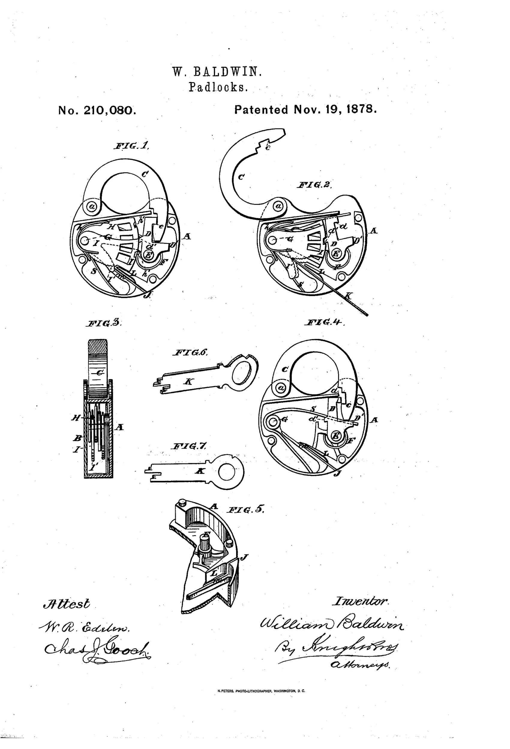
Self-opening padlock with double spring tumblers
⚿ How it works
The lock uses two opposed sets of spring tumblers (H and I) that slide laterally against each other when a flat key with beveled steps is inserted endwise into a narrow guiding groove. The oblique corrugated edges of the tumblers are pressed by the key's tip, moving alternate tumblers up and down until their notches align with the dog's stump, releasing an L-shaped dog (D) from the shackle's undercut notch. A mainspring (S) then throws the hinged shackle (C) upward into the open position. A cast curtain or partition (L) shields the vital tumbler mechanism from view or manipulation through the keyhole, and the narrow guide groove (M) is sized so a pick cannot get sufficient bearing to work the tumblers individually.
⚿ What was claimed
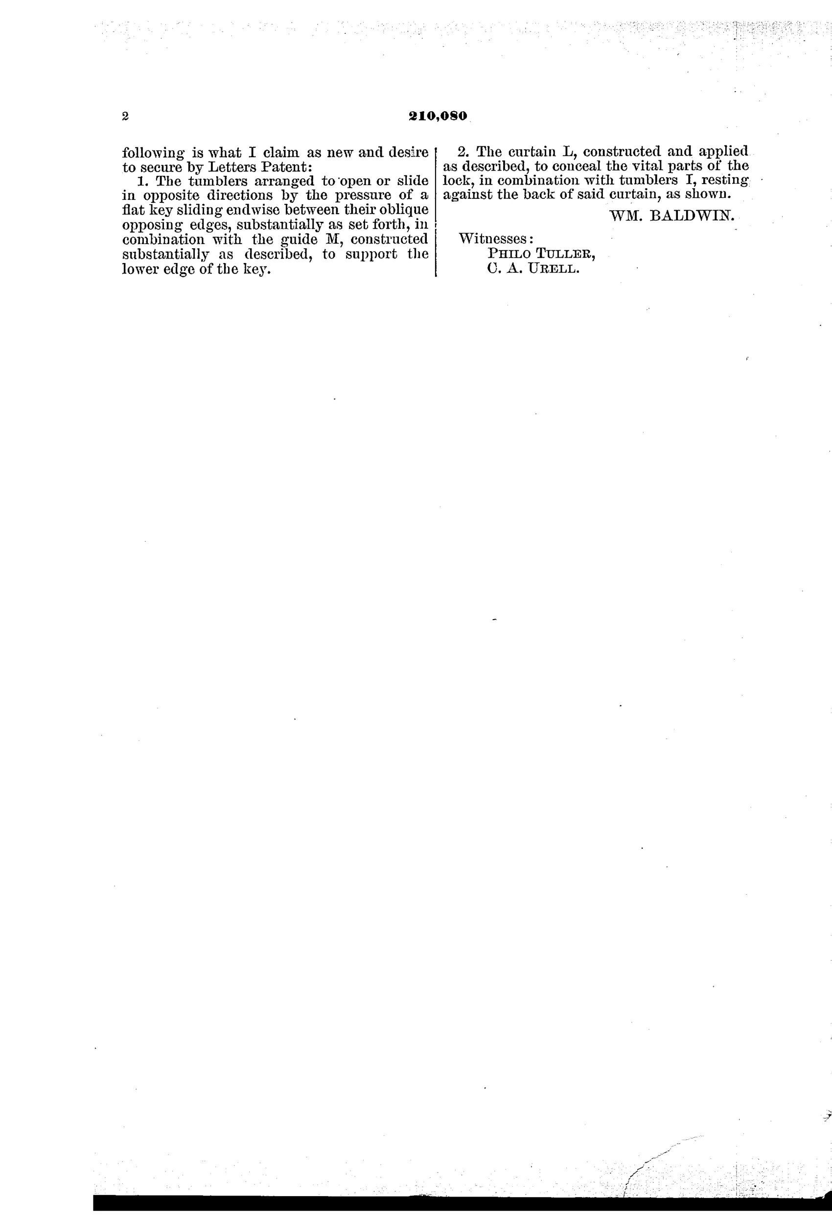
“1. The tumblers arranged to open or slide in opposite directions by the pressure of a flat key sliding endwise between their oblique opposing edges, substantially as set forth, in combination with the guide M, constructed substantially as described, to support the lower edge of the key.”
In plain English: A lock in which a flat key sliding endwise pushes two sets of tumblers in opposite directions along their slanted edges, working together with a guide that supports the key's lower edge.
⚿ In the inventor’s words
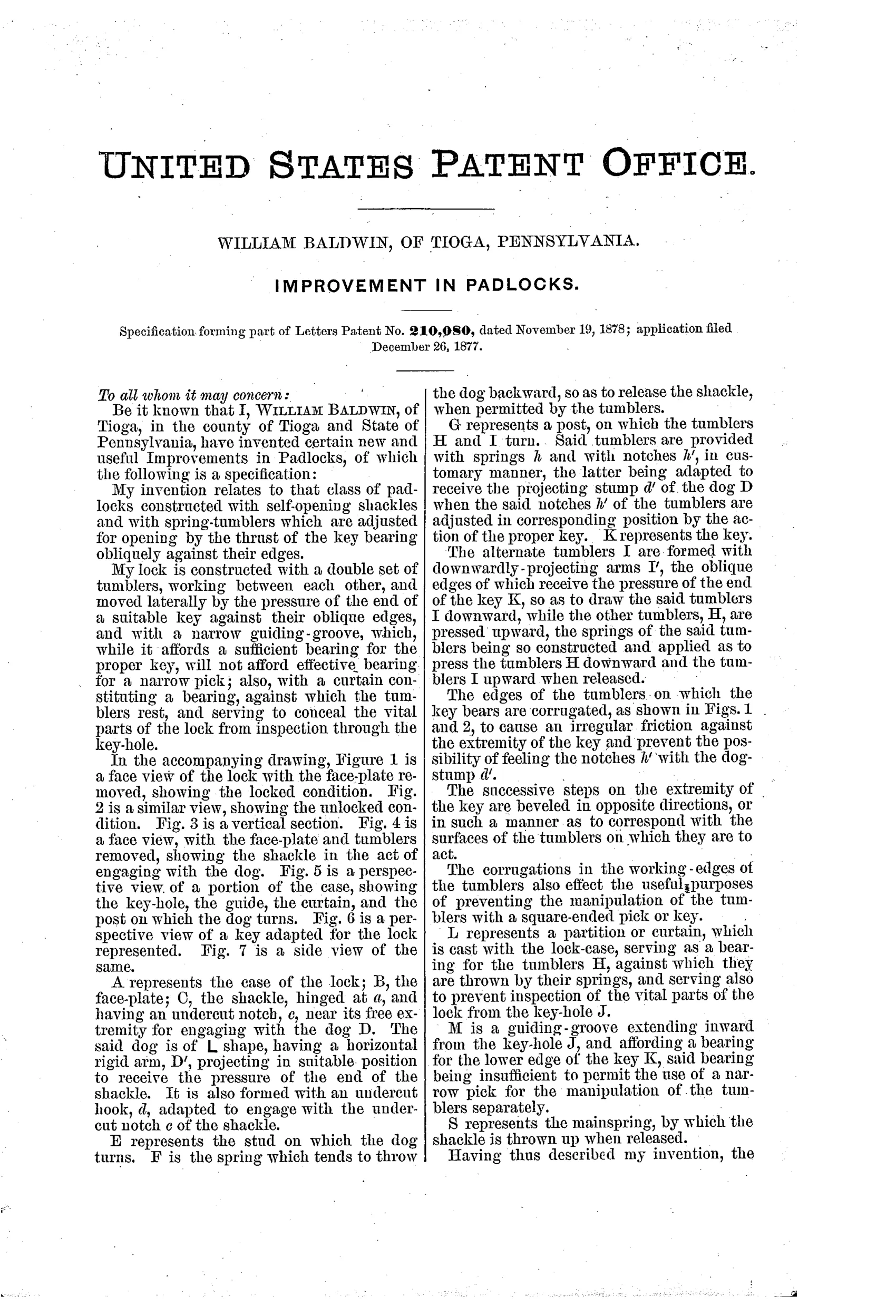
“The corrugations in the working-edges of the tumblers also effect the useful purposes of preventing the manipulation of the tumblers with a square-ended pick or key.”— William Baldwin, from the specification
Fate unknown
The design is producible and akin to push-key locks that were made in quantity, but no specimen attributable to Baldwin's patent is documented; a surviving lock matching the split opposed-tumbler layout would settle it.
⚿ Commentary
Baldwin's core idea is the opposed tumbler stack: two sets of spring tumblers with oblique, corrugated working edges, and a flat stepped key that drives straight in endwise between them. As the key advances, each bevel cams one tumbler up while its neighbor drops, until every notch lines up on the dog's stump. It's the push-key principle — the same family that gives us the six-lever push-key padlocks of the later 1800s — but with the tumblers split into opposing halves, which roughly doubles the number of surfaces a picker has to satisfy at once.
The security thinking is unusually deliberate for 1878. The corrugated edges are there specifically to defeat a square-ended pick, the cast curtain L blinds the keyhole, and the guide groove M is sized so nothing wider than the proper thin key gets useful bearing. Baldwin isn't just adding tumblers; he's reasoning about how an attacker would work the mechanism and closing those paths one by one. The patent's own line about preventing manipulation "with a square-ended pick or key" is the tell.
The self-opening feature — mainspring S flings the shackle up the instant the dog releases — is the crowd-pleaser, and Figs. 1 and 2 show it honestly: same lock, dog engaged versus thrown. Nothing here is implausible to build. Whether anyone in Tioga, Pennsylvania actually built it is another matter; the drawing shows a lock that would have been entirely at home in a hardware catalog, but I know of no marked example.
Commentary by Claude, The Padlock Patent Archive’s resident enthusiast