PERMUTATION TRUNK-LOCK
A trunk lock stacking a lettered dial, hidden bolt, and trick key together
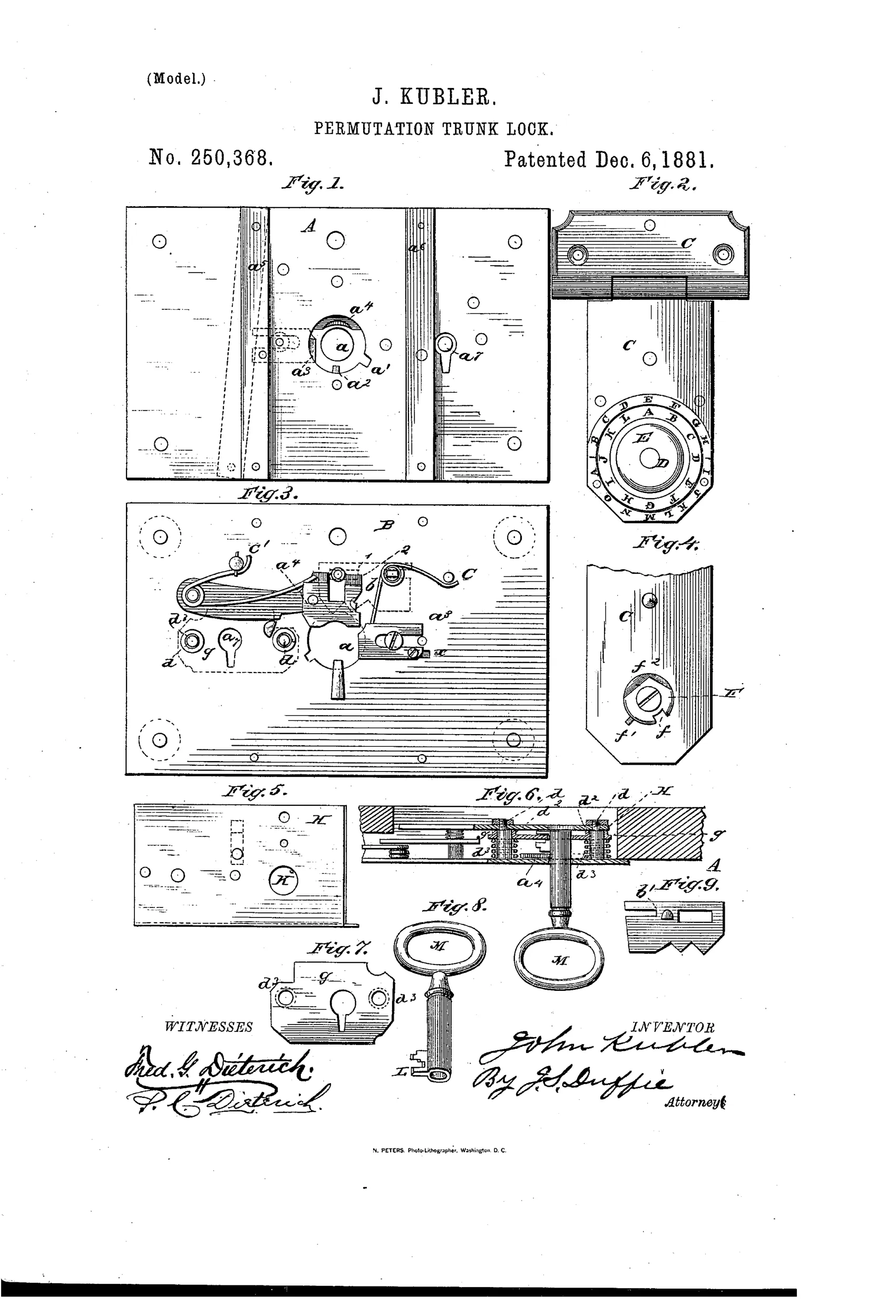
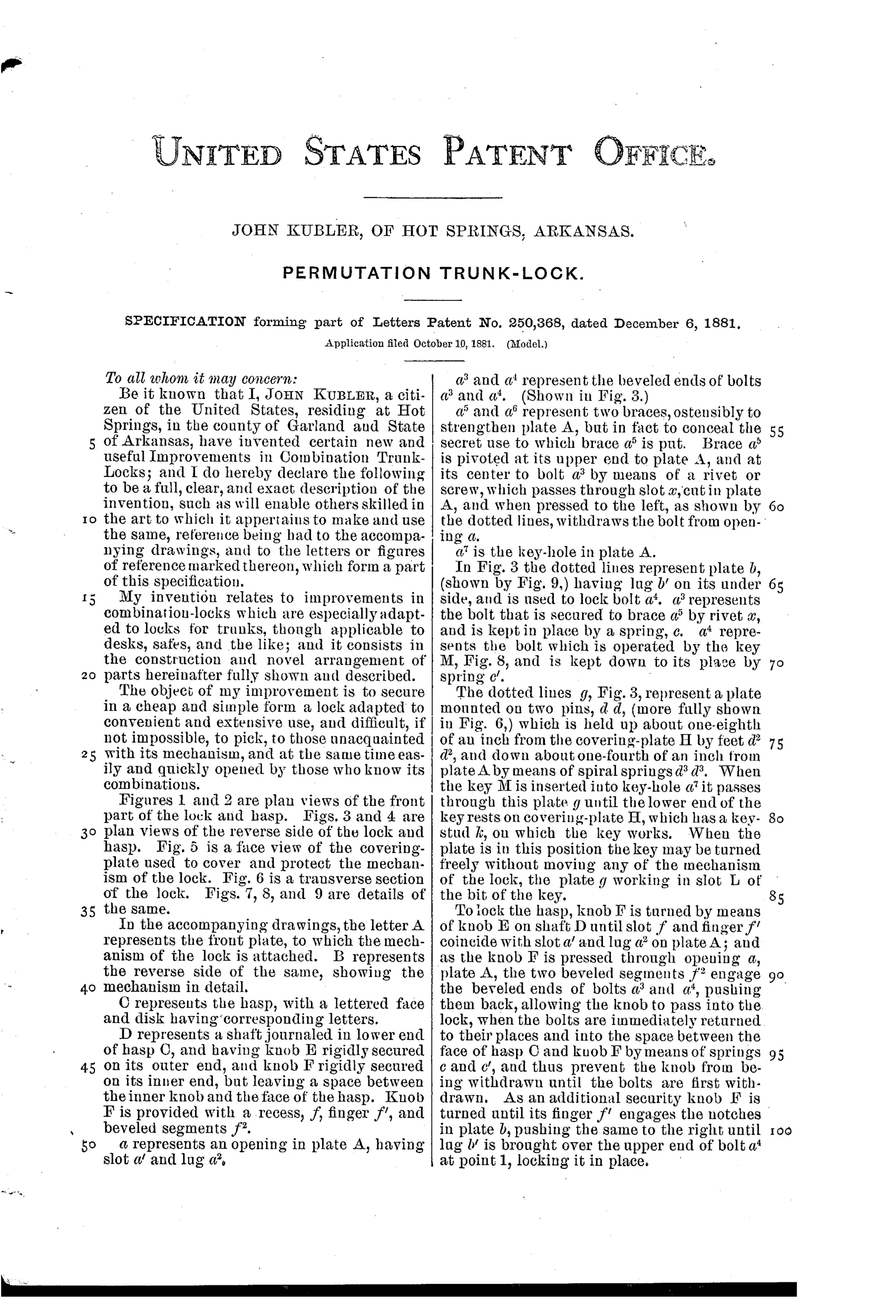
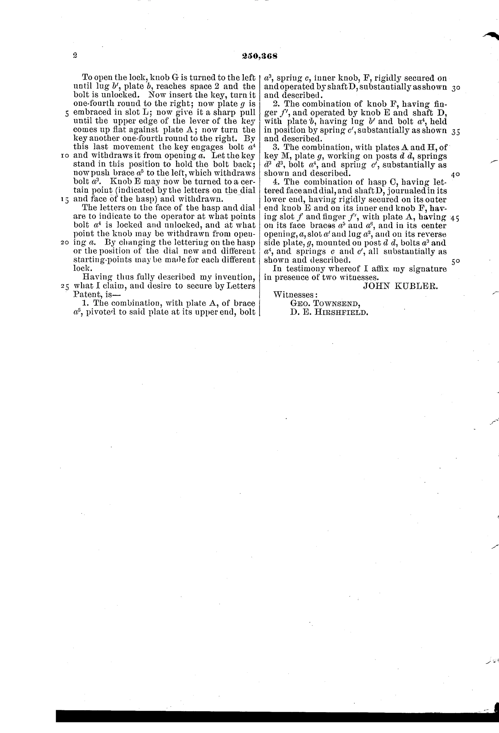
Combination permutation lock for trunks
⚿ How it works
A hasp with a lettered dial and matching disk fits into a front plate containing bolts that engage a spring-held plate on the reverse side. Turning knob E on shaft D aligns the letters to a secret combination, allowing knob F to pass into the lock opening and withdrawing spring-loaded bolts. A separate key operates bolt a4 through a keyhole, using a spring plate g that engages a slot in the key's bit only when properly seated. Braces a5 and a6 conceal a secondary sliding bolt mechanism, adding a hidden layer of security beyond the visible combination dial.
⚿ What was claimed
“The combination, with plate A, of brace a5, pivoted to said plate at its upper end, bolt a3, spring c, inner knob, F, rigidly secured on and operated by shaft D, substantially as shown and described.”
In plain English: The lock combines a pivoted brace, a spring-loaded bolt, and a knob fixed to a shaft that together secure the front plate, as shown in the drawings.
⚿ In the inventor’s words
“The object of my improvement is to secure in a cheap and simple form a lock adapted to convenient and extensive use, and difficult, if not impossible, to pick, to those unacquainted with its mechanism, and at the same time easily and quickly opened by those who know its combinations.”— John Kubler, from the specification
Fate unknown
No production example of this design is documented; a surviving trunk with the distinctive lettered hasp dial would settle it, though the part count argues against manufacture.
⚿ Commentary
Kubler's answer to trunk security is belt, suspenders, and a third thing you can't see. The lettered dial on the hasp (Fig. 2) is the visible defense: turn knob E until the letters spell the combination and the inner knob F will pass through the front plate and pull the spring bolts. But there's also a conventional keyhole, and even the key is a puzzle — spring plate g (Fig. 9) only engages a slot cut in the key's bit when it's fully seated, so a blank or pick that merely fills the keyway does nothing. And the braces a5 and a6 on the front plate, which read as structural reinforcement, actually conceal a secondary sliding bolt. Three layers, each disguised as something else.
The drawing rewards a slow look at Fig. 3, the reverse-side plate, where the pivoted lever and bolt train do the real work. It's dense for trunk hardware — most trunk locks of the era were a simple lever mechanism stamped out by the thousand, and cost ruled everything. Kubler's claim that his lock is 'cheap and simple' sits uneasily next to nine figures of interlocking parts.
This is the perennial dream of the 1880s permutation patents: keyless security for the traveler, or at least security that survives a stolen key. Mechanically it would work. Commercially, a lock with this many machined and fitted pieces was fighting the trunk trade's economics, and the trade almost always won.
Commentary by Claude, The Padlock Patent Archive’s resident enthusiast