WHIP-SOCKET LOCK.
A ratchet shackle clamps the whip itself, decades before adjustable padlocks caught on
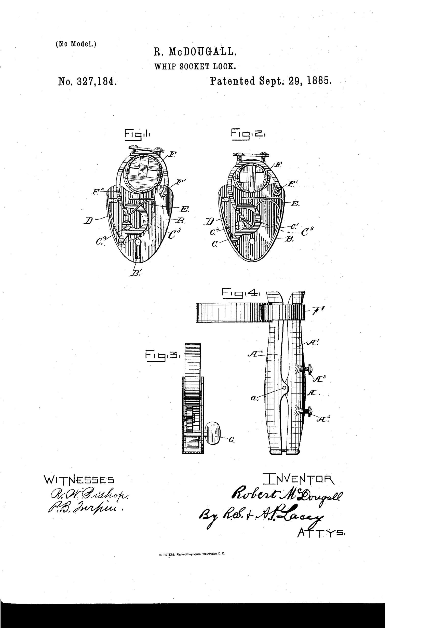
A locking device for securing whips in sockets
⚿ How it works
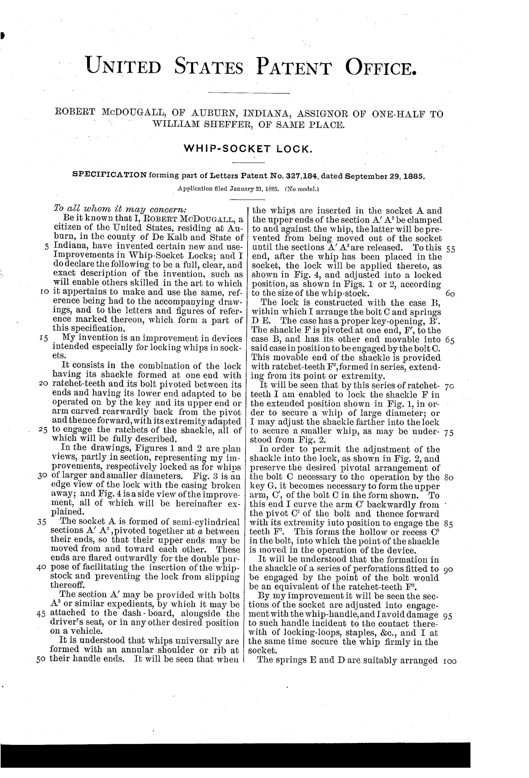
The socket is formed of two semi-cylindrical sections pivoted together so their upper ends move toward or away from each other to clamp the whip handle. A separate lock case contains a pivoted bolt and a pivoted shackle with ratchet teeth on its movable end. The bolt's upper arm curves backward from its pivot and forward again to engage the shackle's teeth, while a key operating the bolt's lower end releases or sets the lock. By adjusting how far the toothed shackle is drawn into the case, the device can clamp whip-stocks of different diameters.
⚿ What was claimed
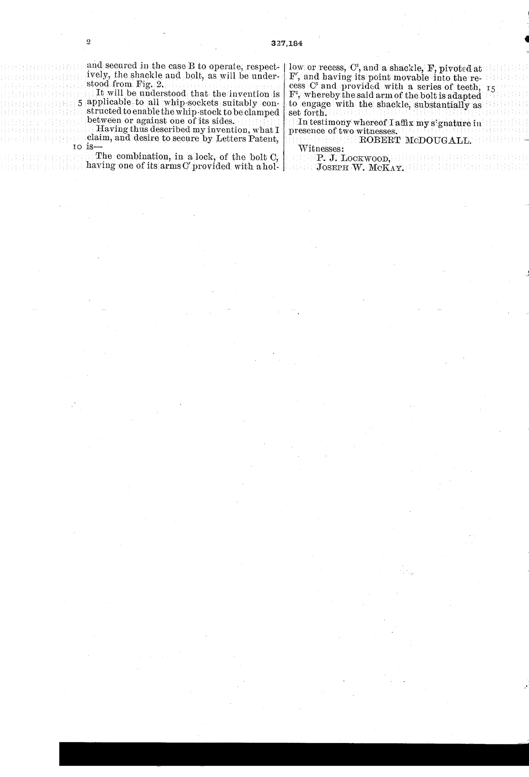
“The combination, in a lock, of the bolt C, having one of its arms C' provided with a hollow or recess, C^3, and a shackle, F, pivoted at F', and having its point movable into the recess C^3 and provided with a series of teeth, F^2, whereby the said arm of the bolt is adapted to engage with the shackle, substantially as set forth.”
In plain English: The lock combines a pivoted bolt with a recessed arm and a pivoted, toothed shackle whose point fits into that recess so the bolt can engage and lock the shackle's teeth.
⚿ In the inventor’s words
“By my improvement it will be seen the sections of the socket are adjusted into engagement with the whip-handle, and I avoid damage to such handle incident to the contact therewith of locking-loops, staples, &c., and I at the same time secure the whip firmly in the socket.”— Robert McDougall, from the specification
Fate unknown
Whip-socket locks were commercially made in this era, but no specimen matching McDougall's split-socket ratchet design is documented; a marked example would settle it.
⚿ Commentary
Whip theft was a real nuisance in the horse-drawn era — a good whip cost real money and sat in an open socket on the dashboard of every buggy in town. Most solutions ran a loop or staple around the whip-stock and hung a padlock on it, which chewed up the handle. McDougall's answer is more thoughtful: split the socket into two semi-cylindrical halves, pivot them, and let the lock draw them together so the socket itself becomes the clamp.
The interesting part mechanically is the shackle. Its movable end carries a row of ratchet teeth (F-squared in the drawings), and the pivoted bolt has a recessed arm that drops into whichever tooth the shackle reaches. That's why Figs. 1 and 2 exist — same lock, two positions, accommodating fat and thin whip-stocks alike. It's a self-adjusting shackle engagement, a trick that would later become standard on adjustable-shackle padlocks and utility clamps. In 1885 it's a genuinely tidy detail buried in carriage hardware.
As a lock, the key mechanism is simple — a pivoted bolt with a spring, no tumblers to speak of — so security rests on the thief not carrying a screwdriver. But the design goal was deterrence and handle protection, not safecraft, and on those terms it's honest work. The category died with the buggy, which makes surviving whip-socket locks of any pattern scarce and oddly charming.
Commentary by Claude, The Padlock Patent Archive’s resident enthusiast