BICYCLE-LOCK.
A shackle lock for bicycles in 1892, bolted to the steering head
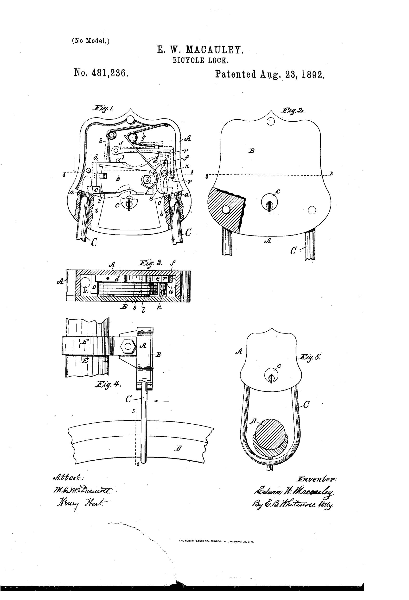
Tumbler lock with a u-shaped hasp for bicycles
⚿ How it works
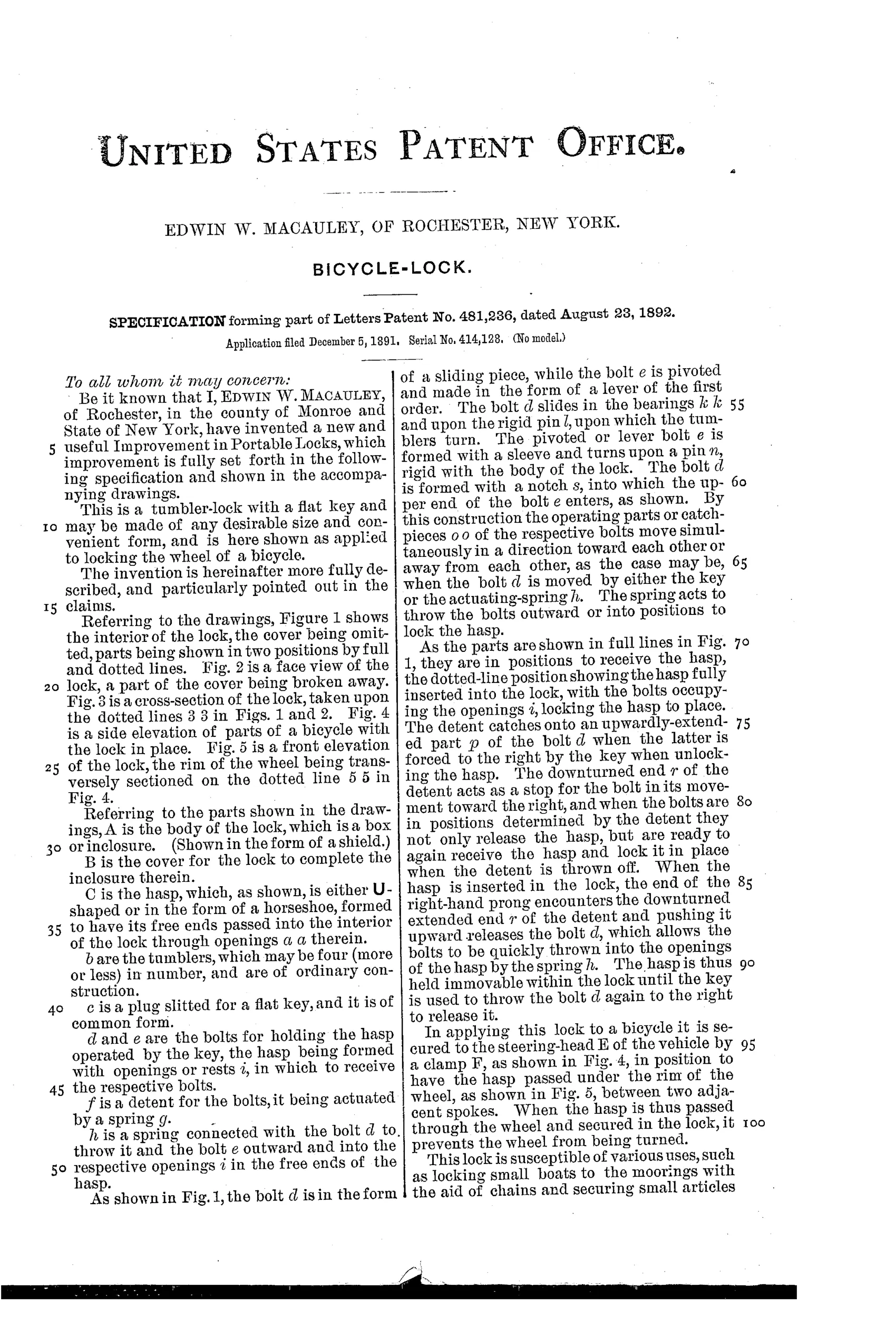
The lock body A holds tumblers b and two bolts, d and e, that operate together. Bolt d slides while bolt e pivots as a lever, joined so they move toward or away from each other simultaneously when the flat key turns plug c. A spring h throws the bolts outward into openings i in the hasp C to lock it, while a spring-actuated detent f catches an upward extension p of bolt d to hold the bolts retracted for unlocking. Inserting the U-shaped hasp pushes on the detent's downturned end r, releasing the bolts so the spring snaps them into the hasp's openings, locking it in place until the key withdraws them again.
⚿ What was claimed
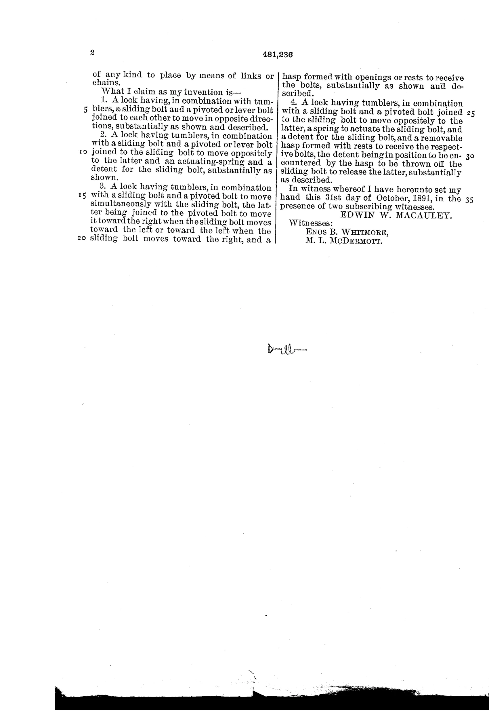
“1. A lock having, in combination with tumblers, a sliding bolt and a pivoted or lever bolt joined to each other to move in opposite directions, substantially as shown and described.”
In plain English: The lock combines tumblers with a sliding bolt and a pivoted lever bolt linked so they move in opposite directions.
⚿ In the inventor’s words
“This lock is susceptible of various uses, such as locking small boats to the moorings with the aid of chains and securing small articles of any kind to place by means of links or chains.”— Edwin W. Macauley, from the specification
Fate unknown
No marked production example is documented; a surviving steering-head lock matching these drawings would settle it.
⚿ Commentary
Strip away the shield-shaped case and this is a recognizably modern idea: a U-shaped shackle passed through the wheel, spring-latched shut on insertion, key-released. Macauley drew it in 1892, when the safety bicycle boom was just cresting and thieves had presumably noticed. Fig. 4 and Fig. 5 show the part most patents of the era skip — the mounting. The lock clamps permanently to the steering head, and the hasp threads down between the spokes and around the rim, immobilizing the front wheel. The lock travels with the bicycle instead of living in a pocket.
The mechanism inside is the interesting compromise. Rather than two sliding bolts, Macauley pairs a slider with a pivoted lever bolt, linked so one key motion drives both into opposite openings in the hasp — his first claim, and a sensible way to grip both legs of a shackle from a single small plug. The detent f is the practical touch: it holds the bolts retracted after unlocking, so the hasp itself trips the release on insertion and the lock snaps shut without the key. That self-locking behavior is exactly what shackle padlocks settled on decades later.
As a padlock it's a footnote; as a bicycle lock it's an early, thoughtful entry. The flat key and simple tumblers wouldn't stop a determined thief, but the architecture is sound and ahead of its moment.
Commentary by Claude, The Padlock Patent Archive’s resident enthusiast