LOCKING-CHAIN
The lock never feels the pull: a chain that hides its own weak link
A locking chain with an open-link lock
⚿ How it works
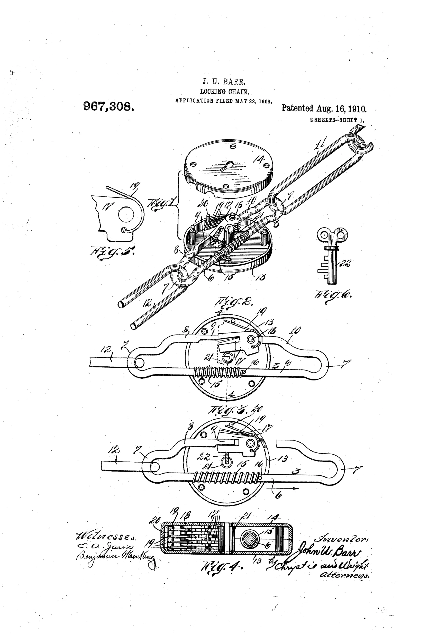
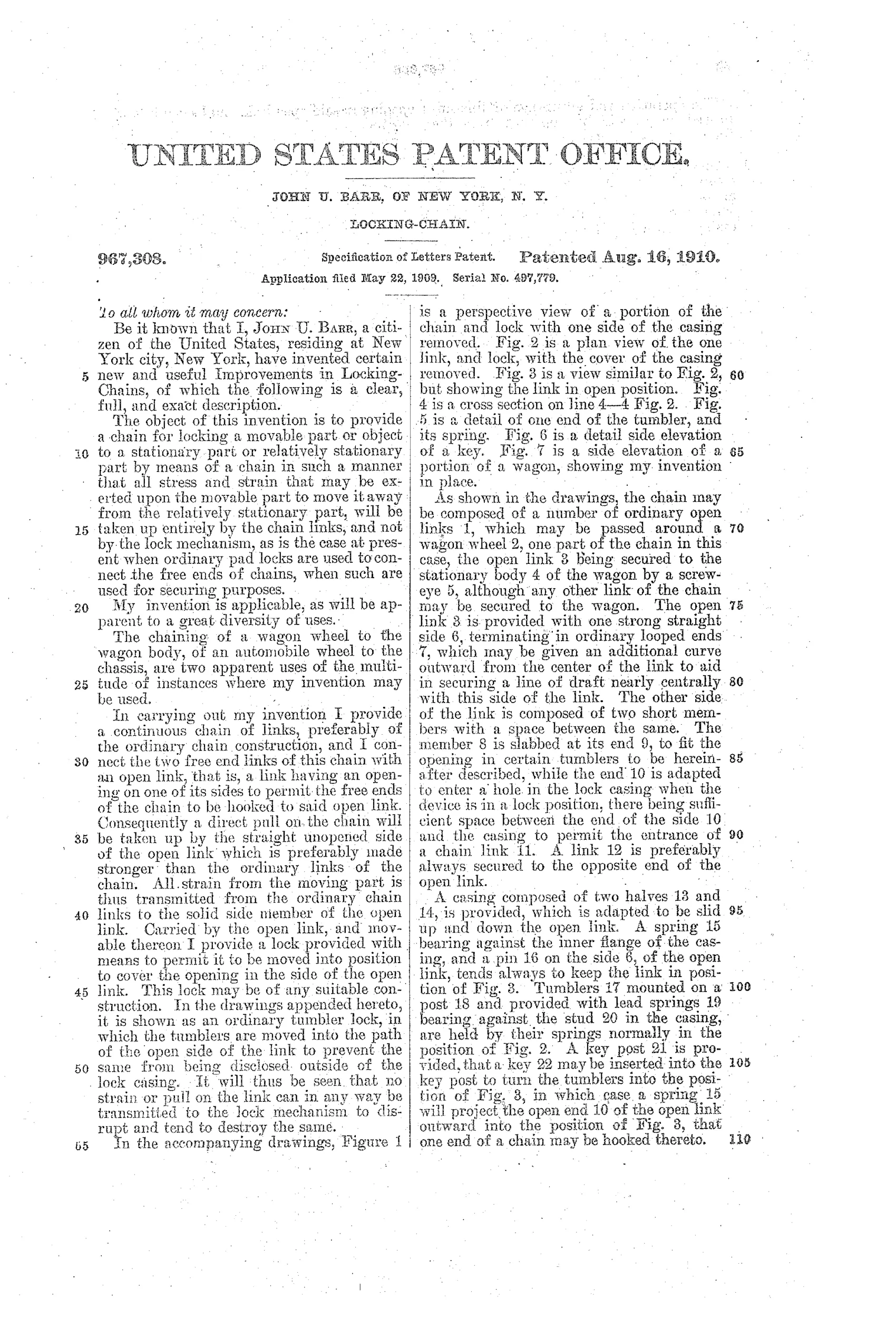
A continuous chain of ordinary closed links is joined by one open link that has a gap on one side for hooking the chain's free ends. A sliding two-piece casing moves over the open link to cover this gap, and spring-loaded tumblers mounted in the casing move into the path of the open side to prevent it from being uncovered. A key inserted into a key post turns the tumblers out of the way so a spring can push the open end outward for hooking or unhooking a chain link. Because the open link's solid straight side carries the pulling strain, no force from the chain is ever transmitted to the lock mechanism itself.
⚿ What was claimed
“The herein described continuous chain composed of a number of closed links and an open link, a lock casing, the open link extending through the lock casing, the lock casing adapted to be moved to cover the opening in said open link, and locked in said position.”
In plain English: The invention is a chain made of closed links plus one open link, fitted with a sliding lock casing that covers and locks the open link's gap.
⚿ In the inventor’s words
“It will thus be seen that no strain or pull on the link can in any way be transmitted to the lock mechanism to disrupt and tend to destroy the same.”— John U. Barr, from the specification
Paper patent — likely never produced
No production locking chain matching this open-link, sliding-casing design is known; a marked specimen would change the verdict, but none is documented.
⚿ Commentary
Barr's insight here is worth stating plainly, because it's the whole patent: in any chained lock, the lock is usually the part you attack, so he arranged things so the lock carries no load at all. The chain is continuous except for one open link with a gap on one side. The straight, solid side of that link takes all the pulling strain; the sliding casing merely covers the gap and holds itself in place with spring-loaded tumblers. Yank on the chain as hard as you like — the lock mechanism only ever has to resist being slid open, not being torn apart. His own line says it best: no strain on the link 'can in any way be transmitted to the lock mechanism.'
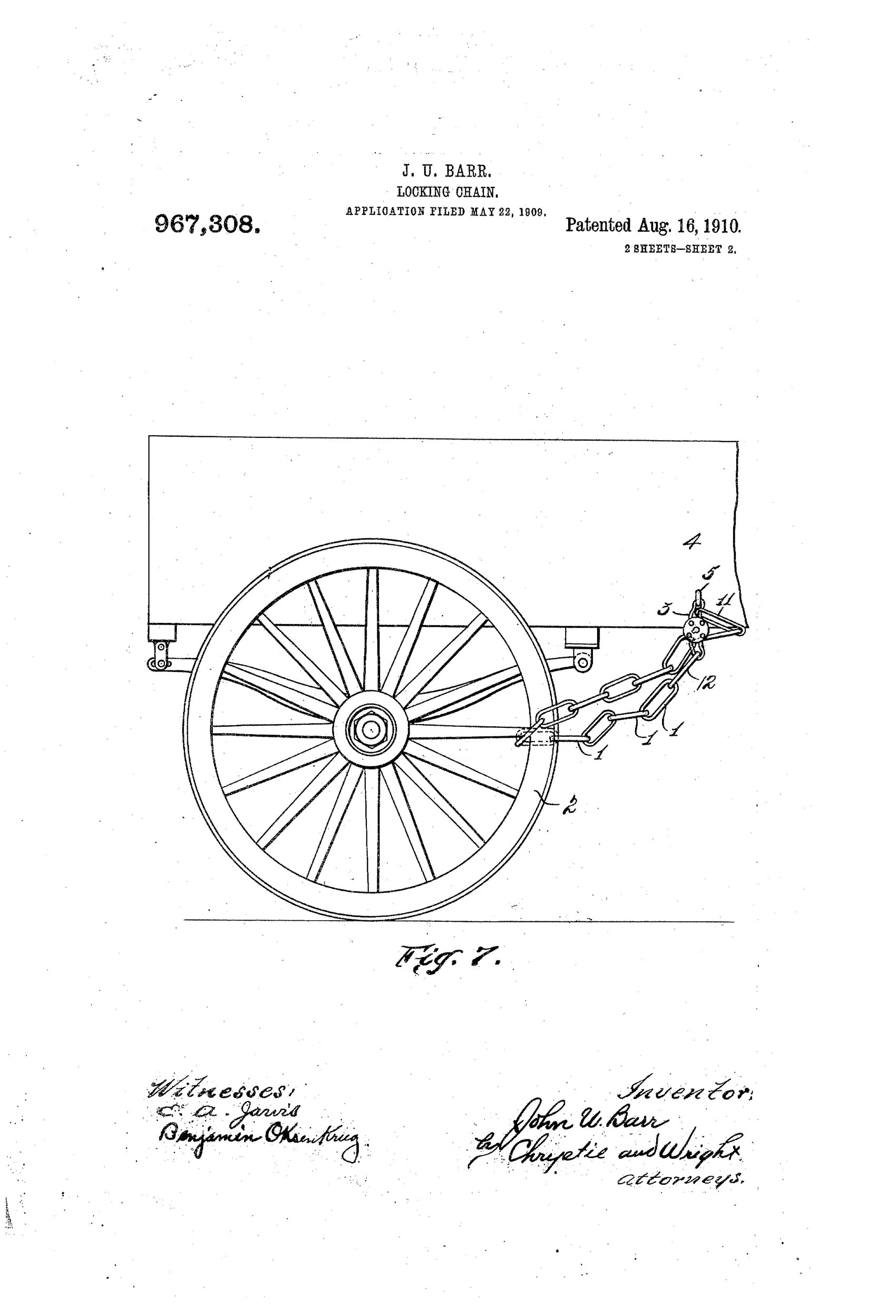
Figs. 2 and 3 show the trick clearly if you look at the gap in the link — covered and locked in one, exposed for hooking in the other, with the key post and tumblers between. Fig. 7 gives the game away on the intended market: this is a wagon wheel lock, chaining wheel to body in 1910, right at the moment such chains were about to migrate from wagons to automobiles.
The tumbler work itself is modest, and covering a gap is not the same as making it strong — a determined attack on the casing seams would still be the obvious route. But as a piece of load-path thinking, it's a genuinely tidy answer to the perennial chain-lock problem, and it sits ahead of the flood of tire-and-rim locks the automobile era would bring.
Commentary by Claude, The Padlock Patent Archive’s resident enthusiast