IMPROVEMENT IN PADLOCKS
A sliding J-hook shackle instead of a hinge — the whole lock in three bolts
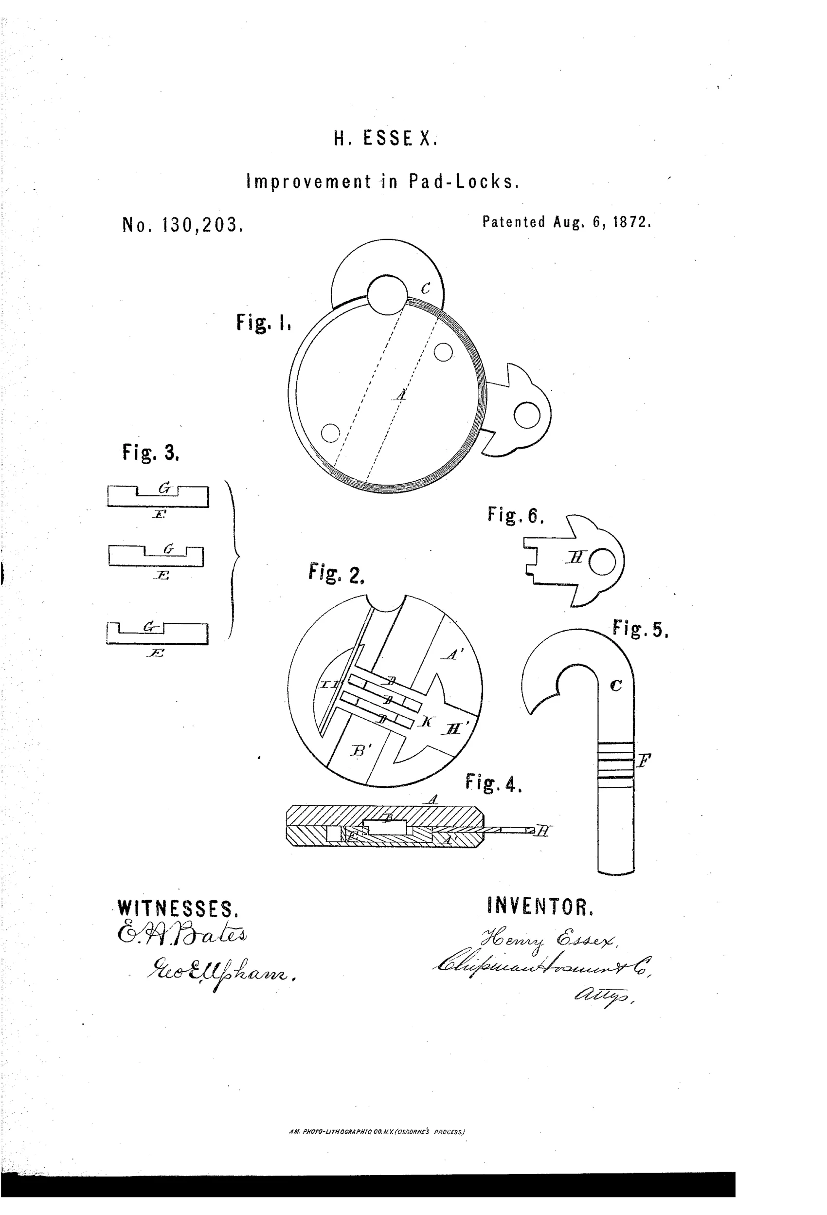
A sliding-bolt j-shaped staple padlock
⚿ How it works
The padlock case is formed of two circular halves, A and A prime, joined together with a recess to receive the shank of a J-shaped staple, C. Grooves traverse the recess at right angles and hold sliding bolts, E, which engage corresponding grooves cut into one side of the staple to secure it in place. The staple slides in and out rather than pivoting on a hinge, and a key inserted through a keyhole channel pushes back the bolts, aligning recesses cut in them so the staple shank can pass through and be withdrawn or inserted. A spring housed in a semicircular recess presses the bolts forward when the key is removed, locking the staple in place again.
⚿ What was claimed
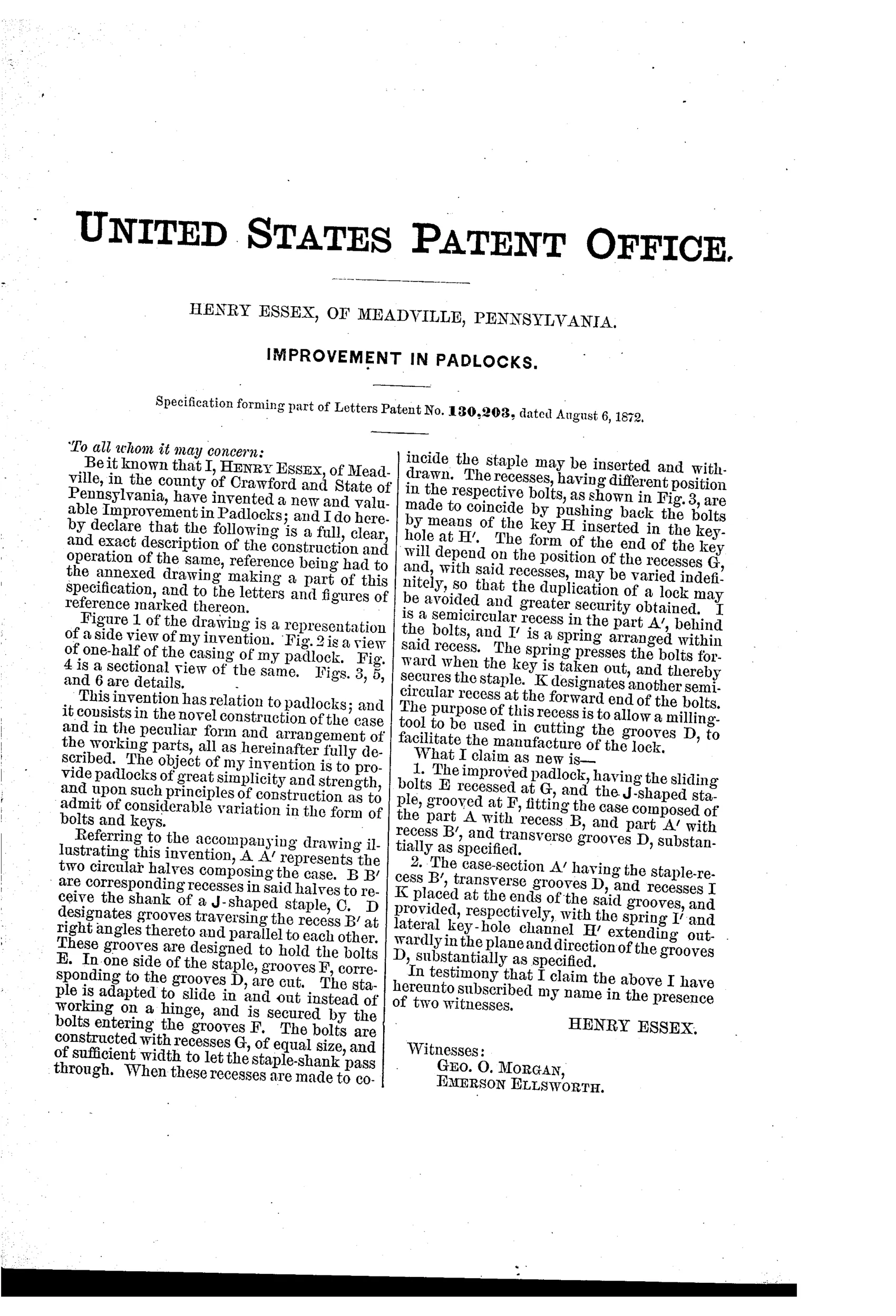
“The improved padlock, having the sliding bolts E recessed at G, and the J-shaped staple, grooved at F, fitting the case composed of the part A with recess B, and part A' with recess B', and transverse grooves D, substantially as specified.”
In plain English: The padlock uses sliding, recessed bolts working against a grooved J-shaped staple, all fitted within a two-part case having matching recesses and crosswise grooves.
⚿ In the inventor’s words
“The object of my invention is to provide padlocks of great simplicity and strength, and upon such principles of construction as to admit of considerable variation in the form of bolts and keys.”— Henry Essex, from the specification
Fate unknown
Essex was an independent Meadville inventor with no known assignee or production tie; a surviving round sliding-staple lock matching Fig. 1 would settle it.
⚿ Commentary
Most padlocks of 1872 secured a pivoting shackle at one heel. Essex throws that out: his J-shaped staple slides bodily in and out of the round case, and it is held by a stack of flat sliding bolts whose noses drop into grooves cut across the staple's shank. The key does one simple thing — it pushes the bolts back until the recesses cut into each bolt line up into a clear channel, and the staple pulls free. Let go of the key and a single spring shoves the whole stack forward again. Fig. 3 is the part a casual reader skips past and shouldn't: three bolts with the recess G cut at three different positions. That is the keying system. Vary where the notches sit, vary the key bit to match, and one pattern of parts yields many differs.
This is the same logic as the Scandinavian-pattern lock and the later six-lever push-key designs — stacked flat elements, each demanding its own lift or push — but Essex applies it to a straight-pull staple rather than a swinging one. His stated goal, 'great simplicity and strength,' is honest: a grooved shank gripped at multiple points along its length is genuinely hard to pry, harder than a single heel pivot.
The weakness is the flip side of the simplicity: if all the bolts are pushed together by one flat bit, the security lives entirely in the notch spacing, and a bent wire probing the channel could do the key's job. Still, as a piece of 1870s mechanical reasoning it is clean, cheap to make, and ahead of the crowd it ran with.
Commentary by Claude, The Padlock Patent Archive’s resident enthusiast