The Padlock Patent Archive

Three centuries of keeping things shut

Padlock

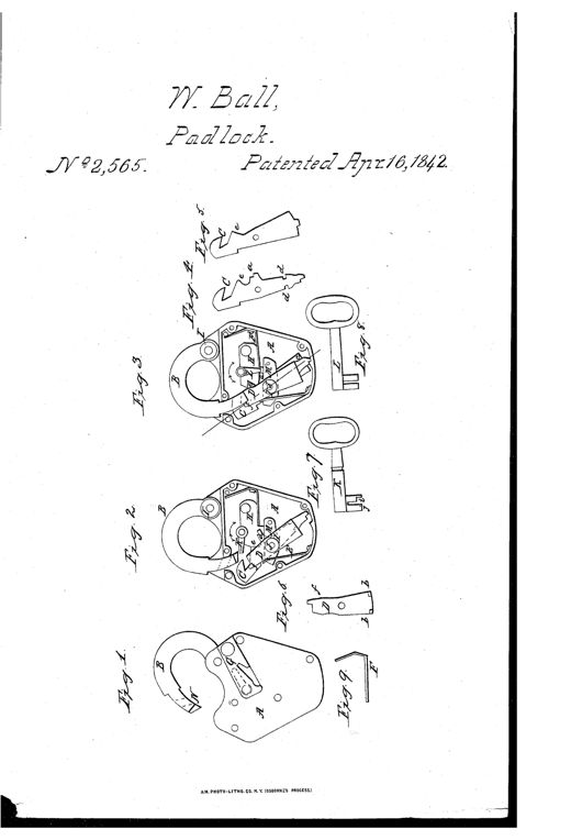
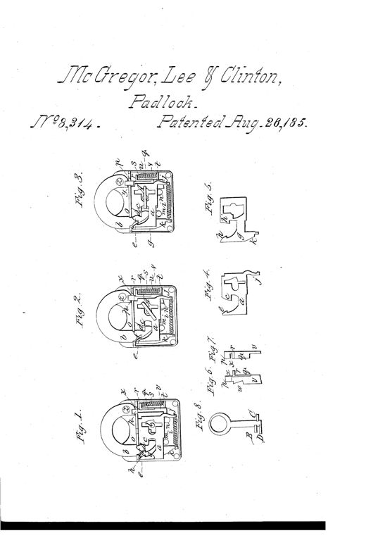
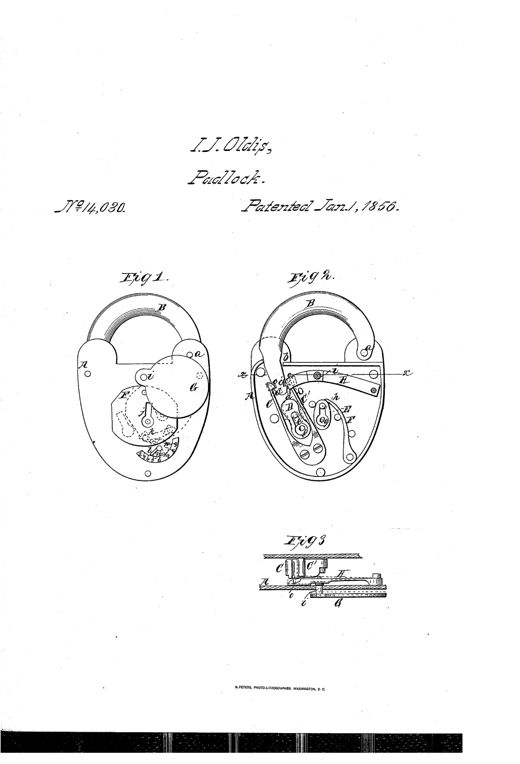
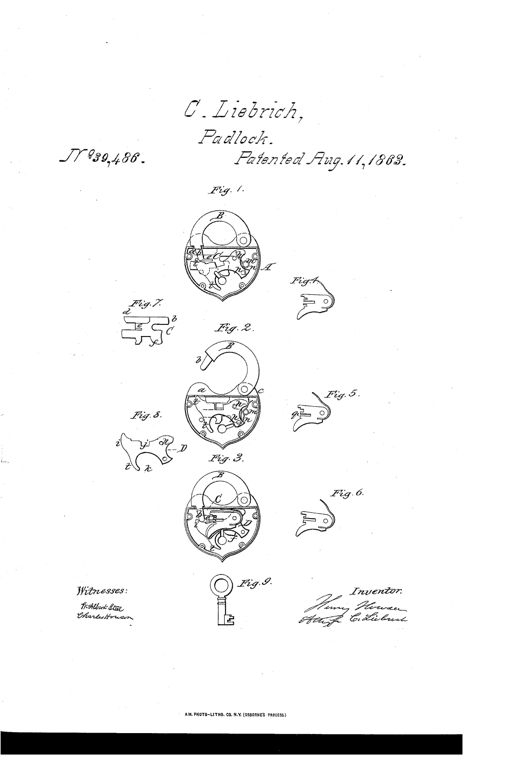
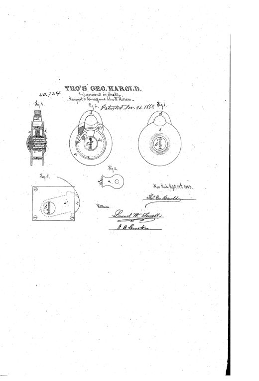
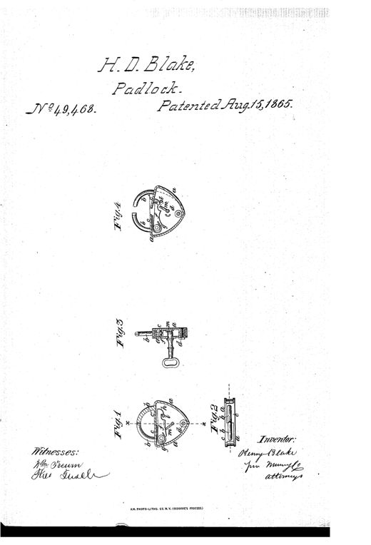
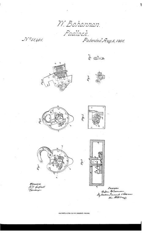
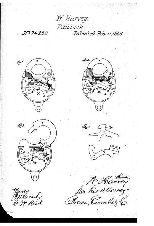
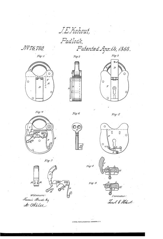
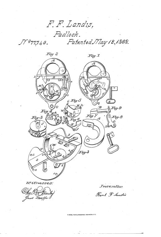
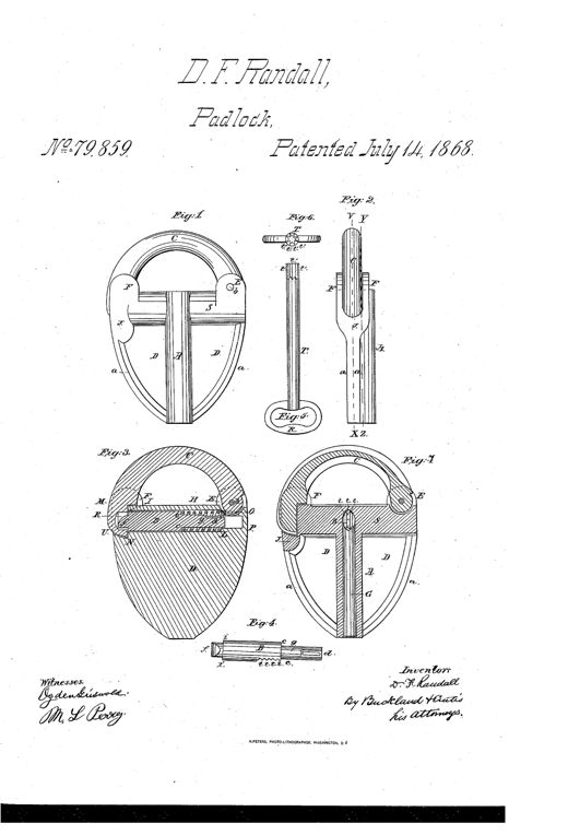
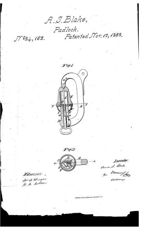
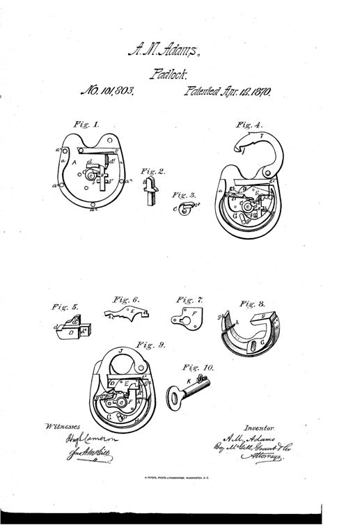
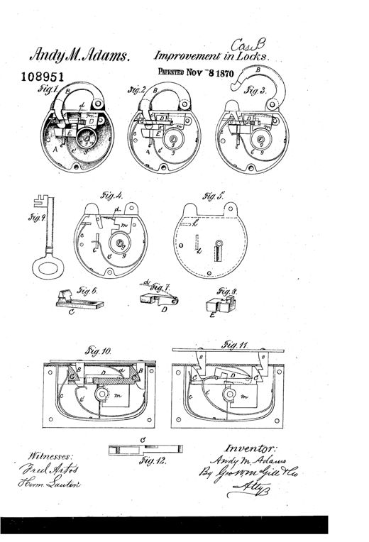
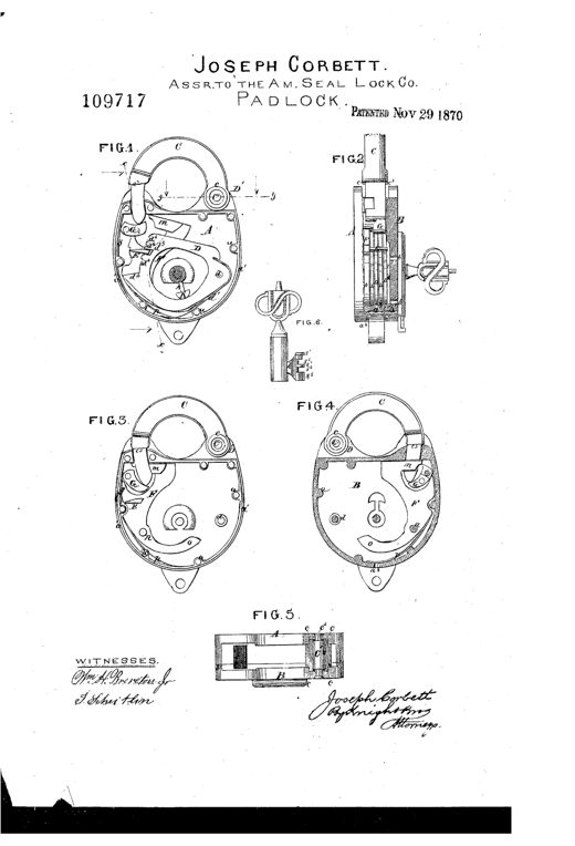
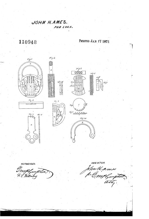
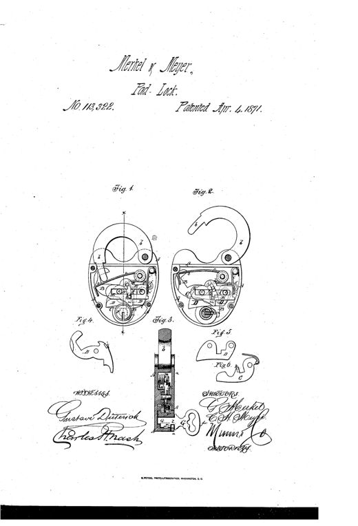
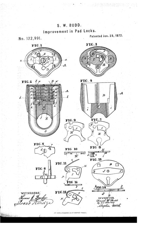
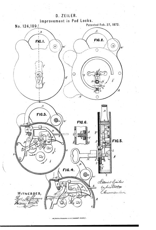
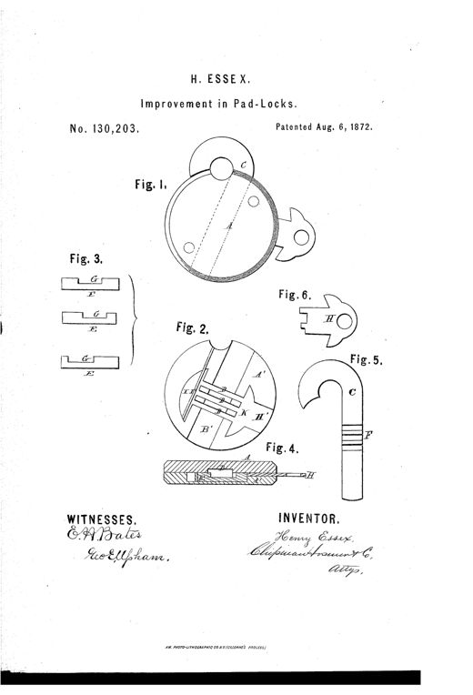
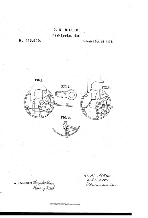
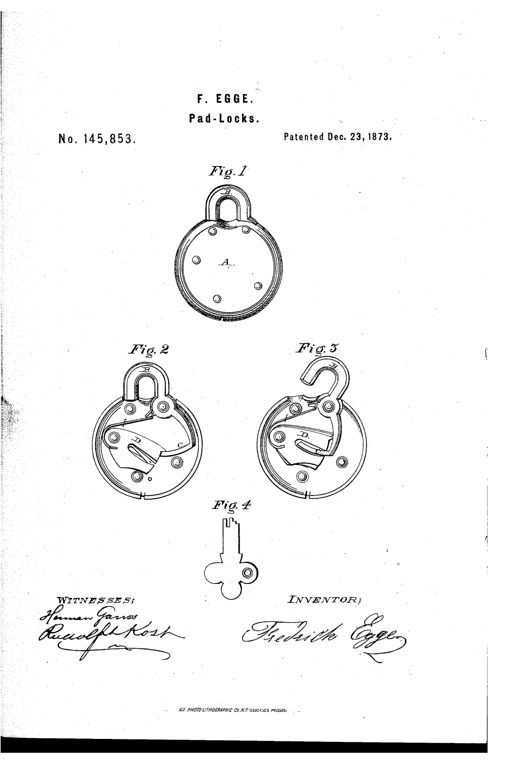
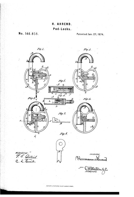
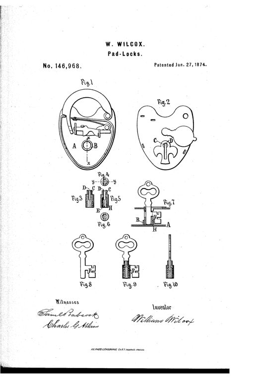
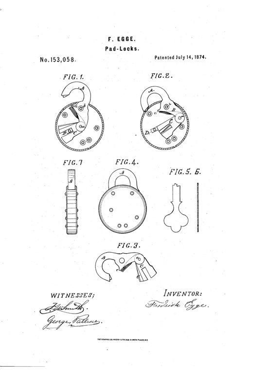
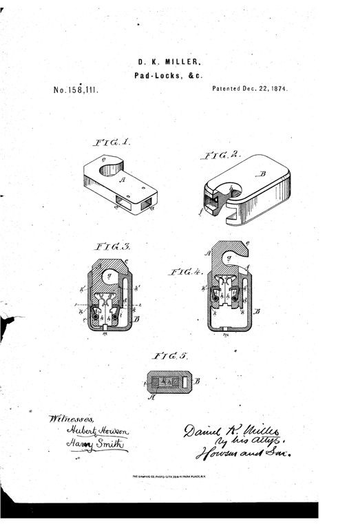
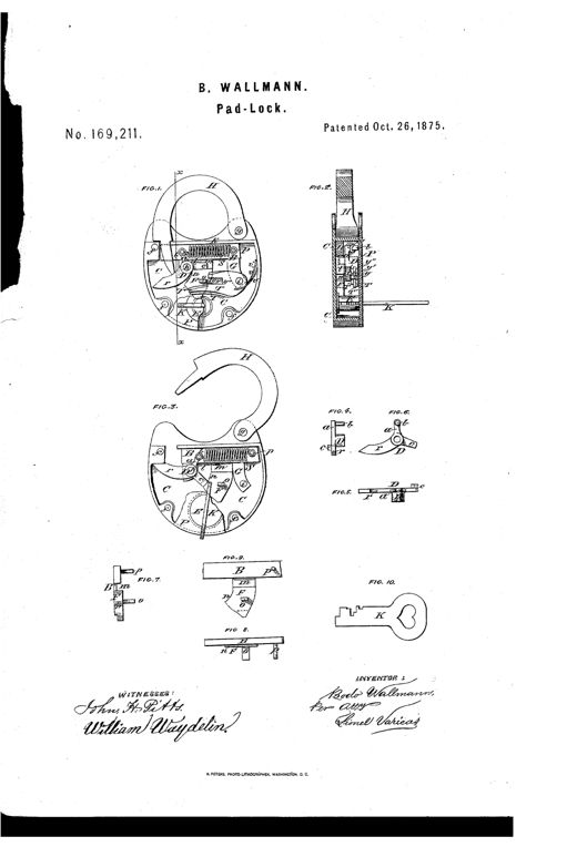
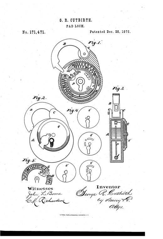
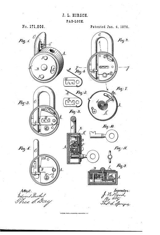
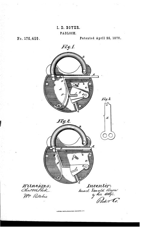
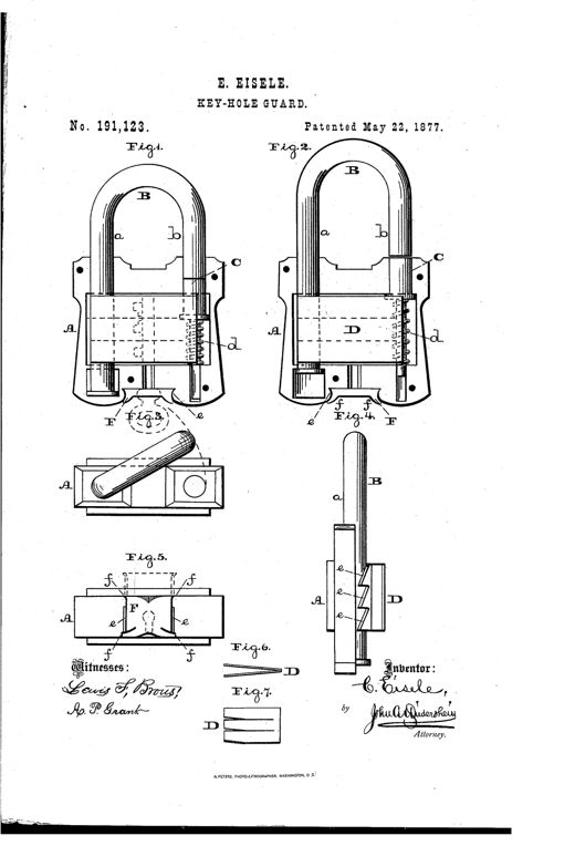
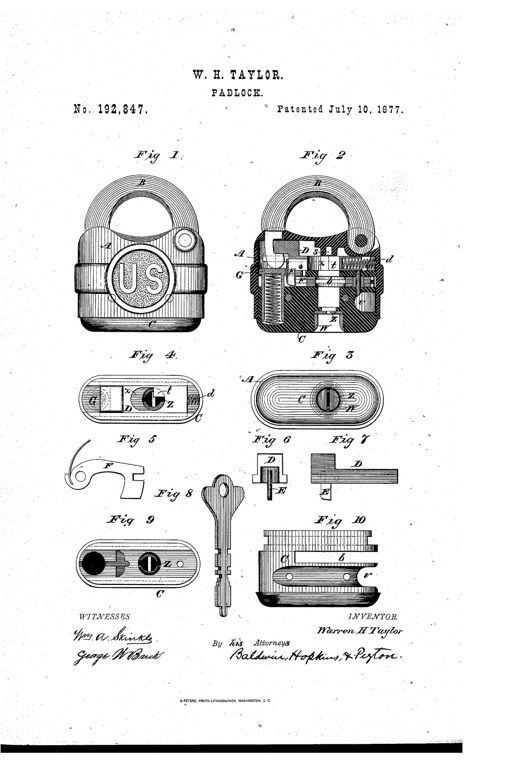
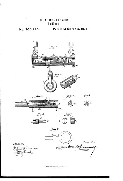
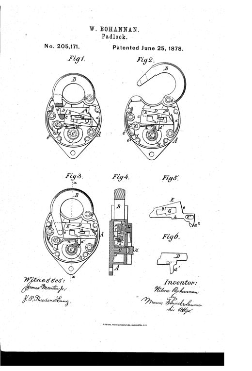
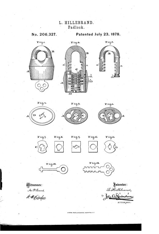
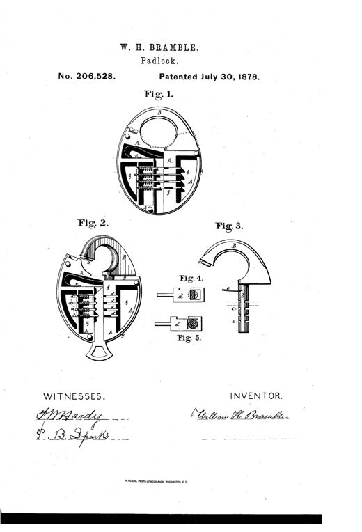
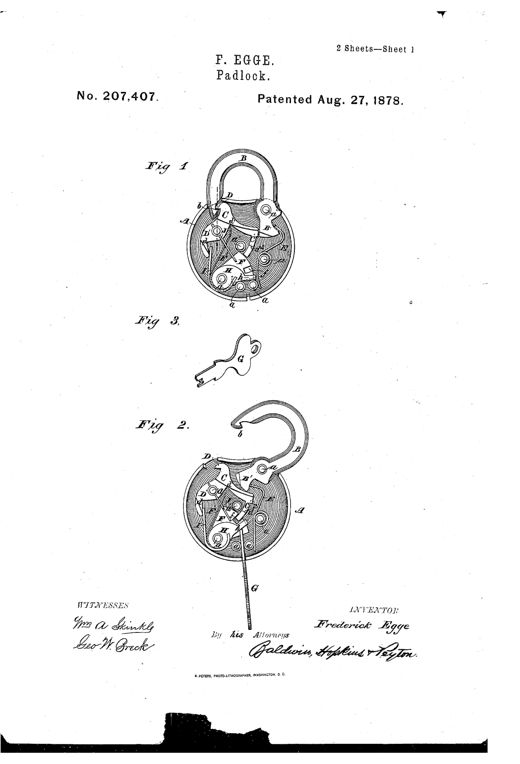
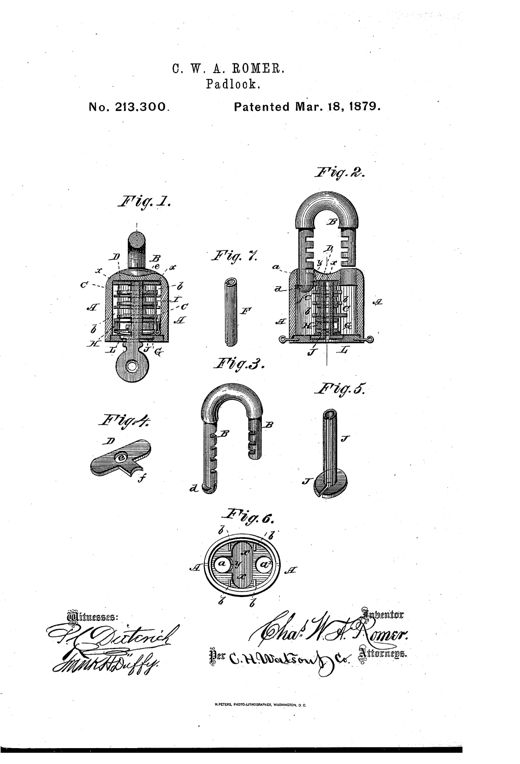
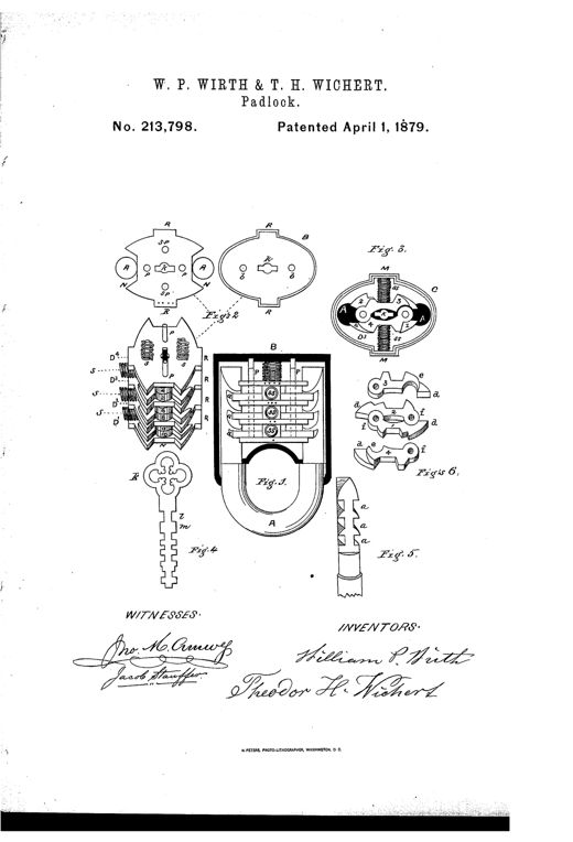
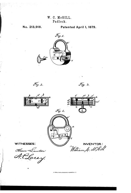
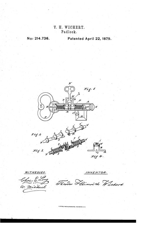
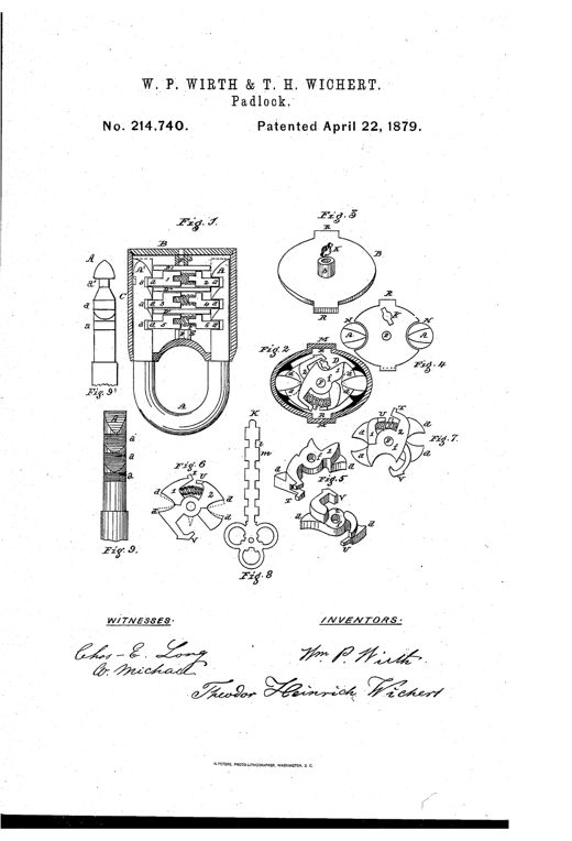
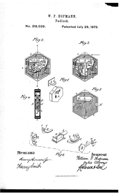
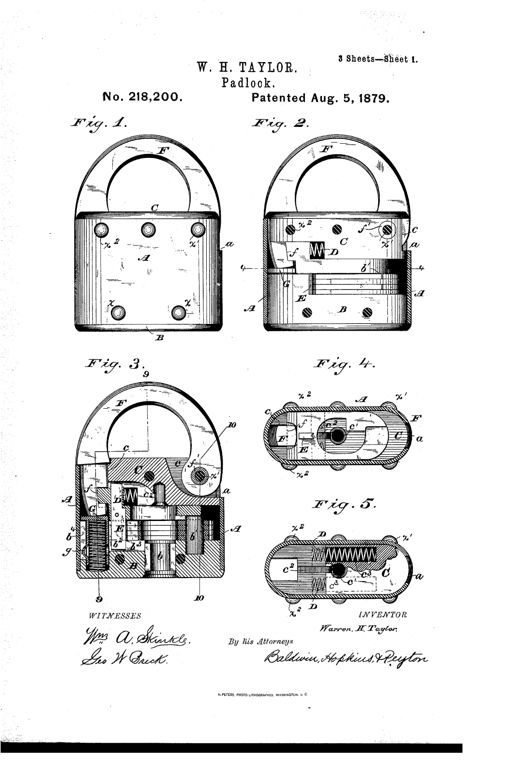
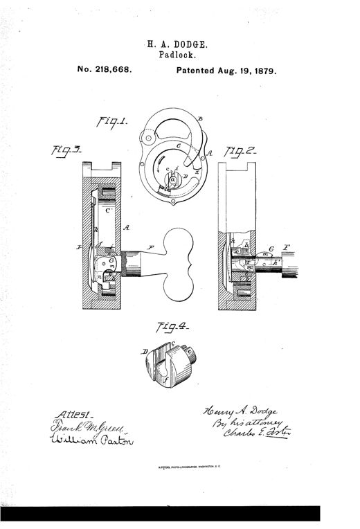
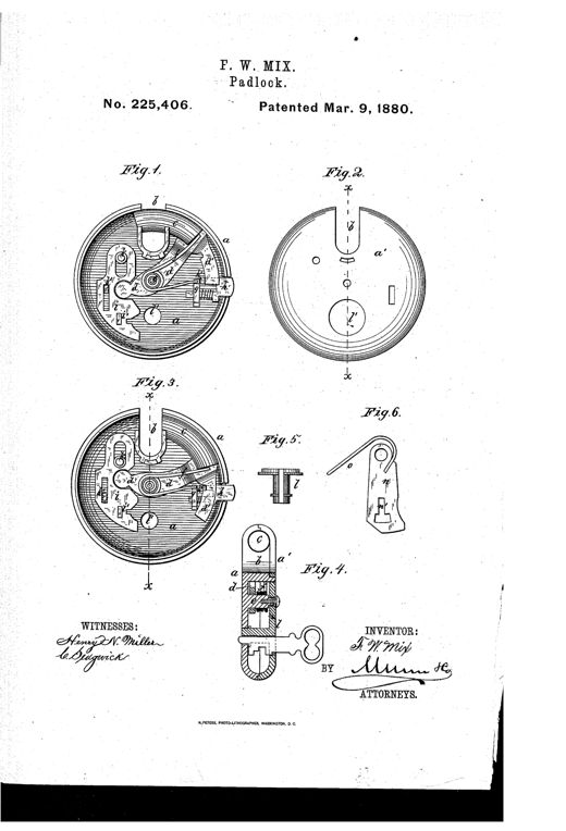
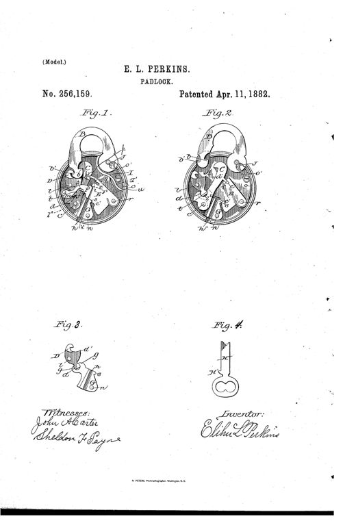
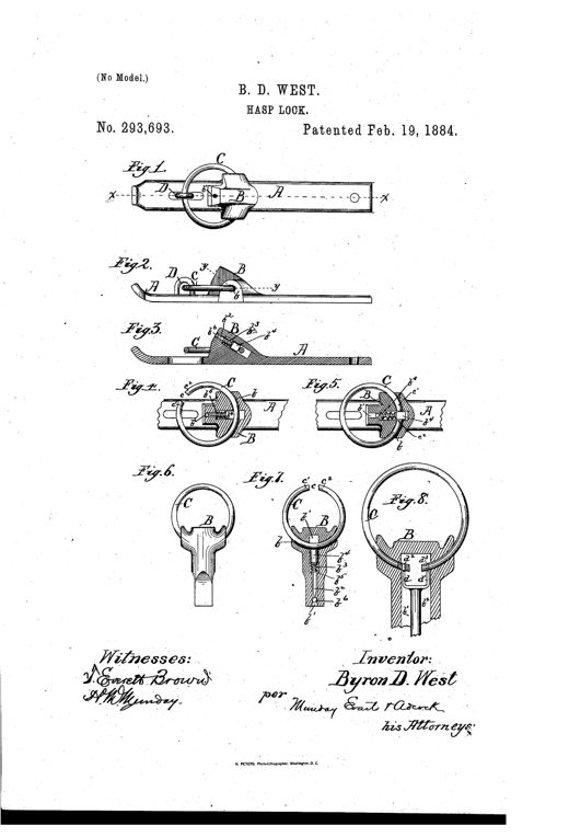
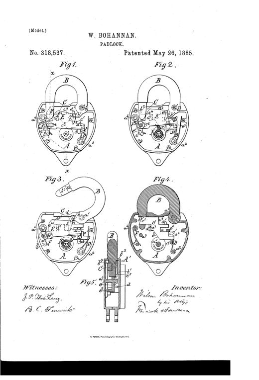
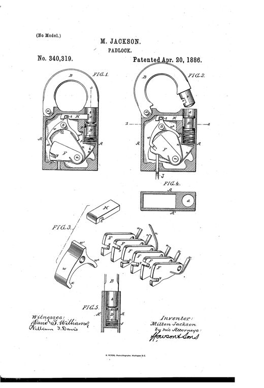
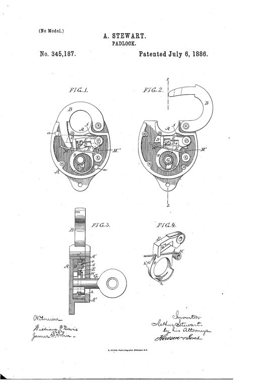
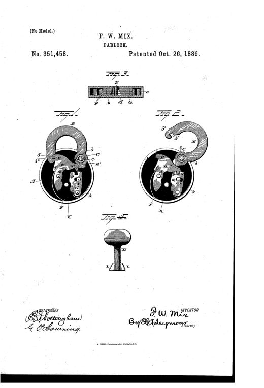
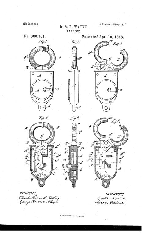
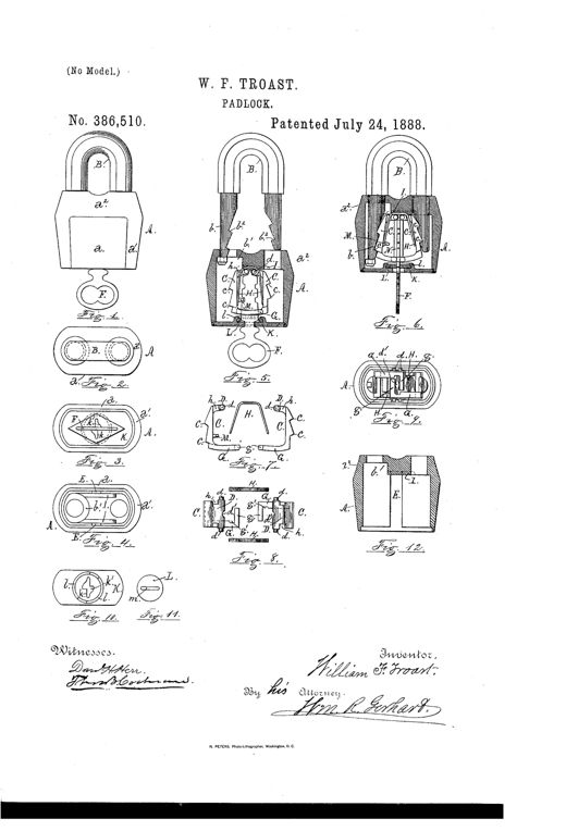
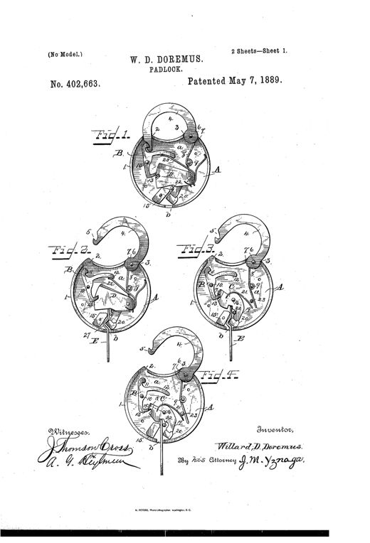
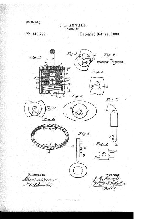
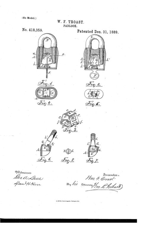
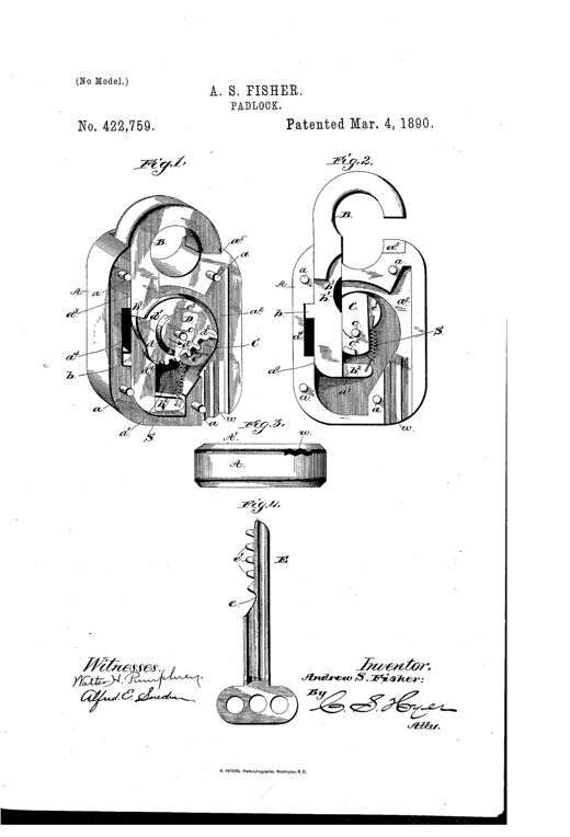
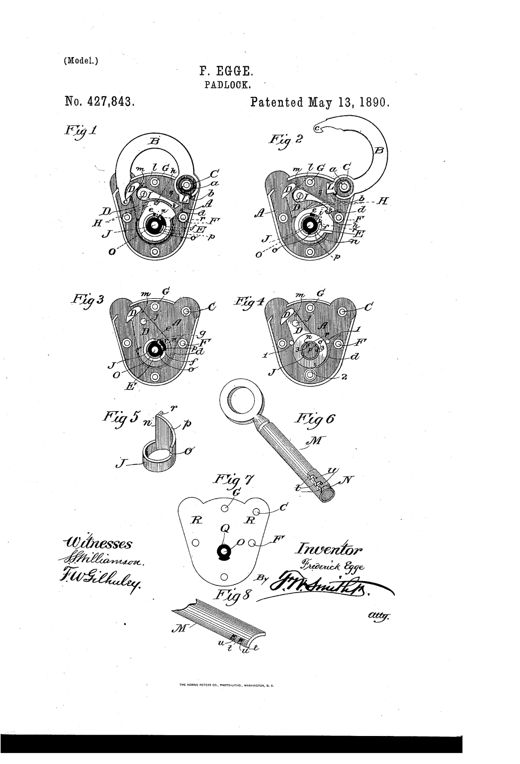
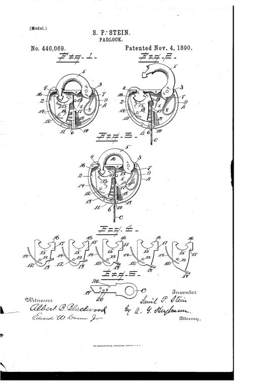
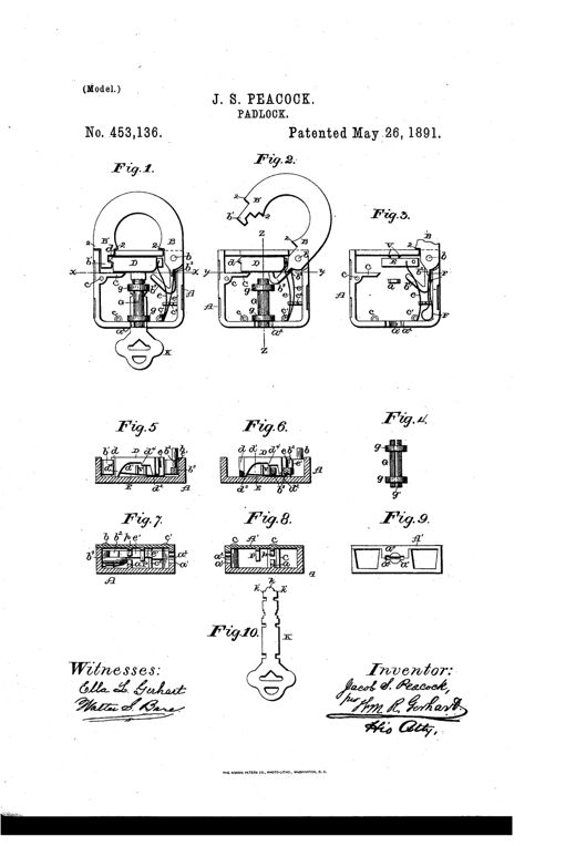
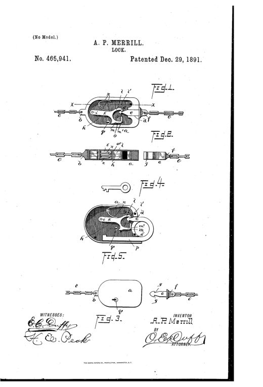
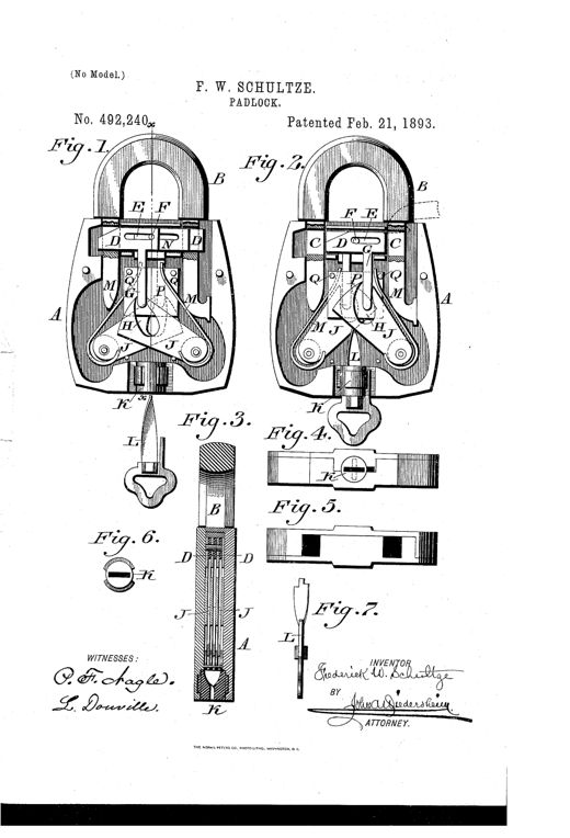
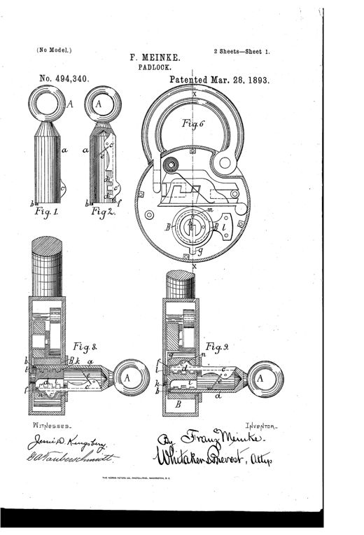
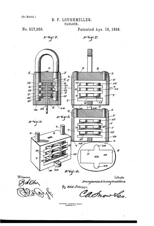
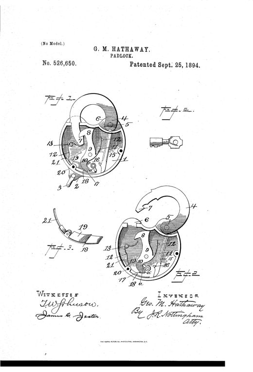
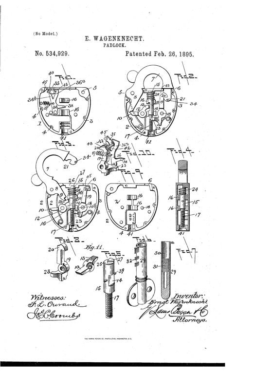
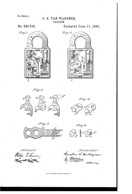
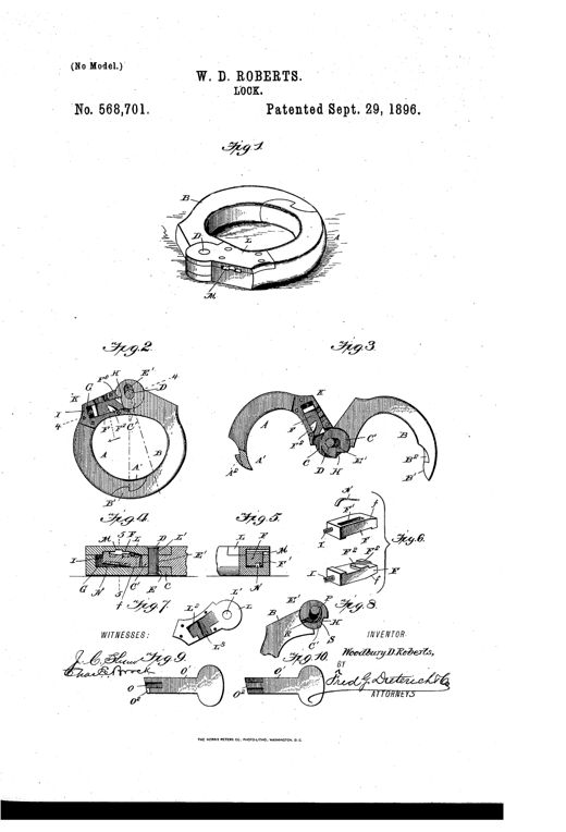
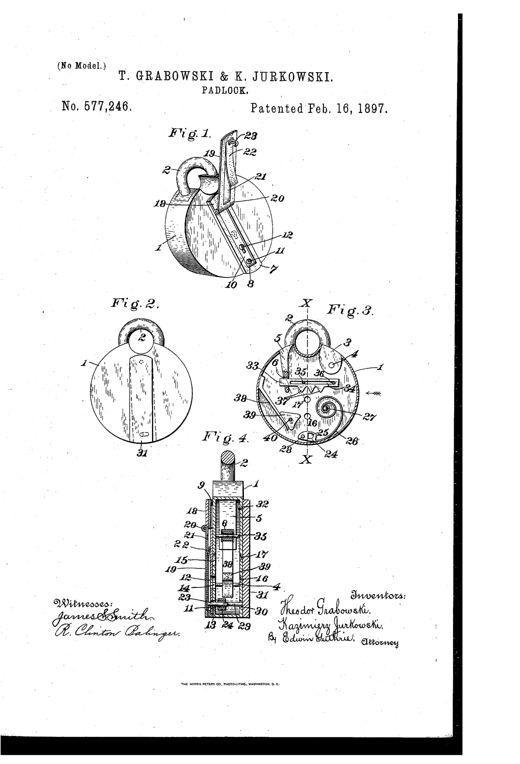
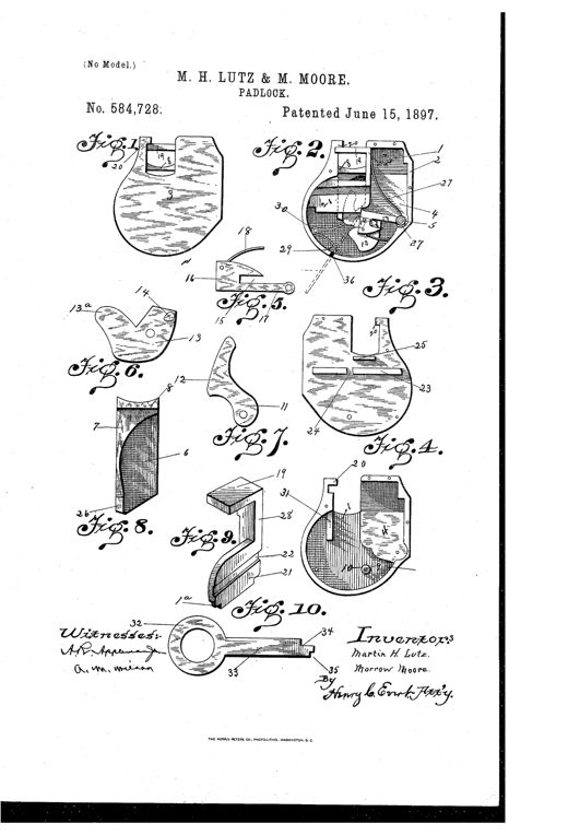
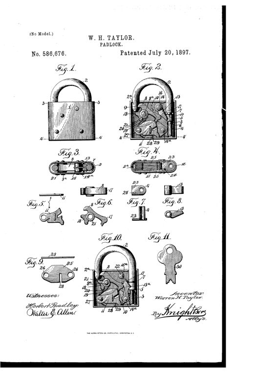
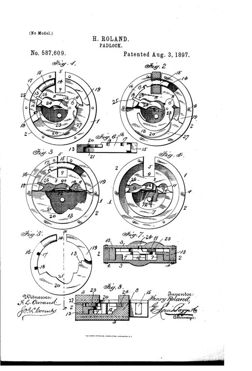
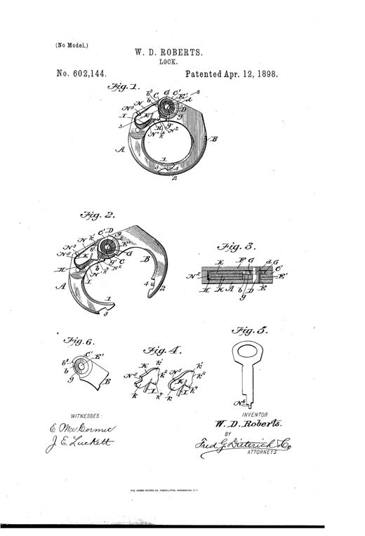
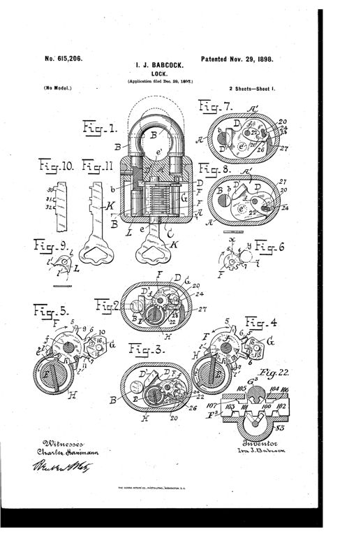
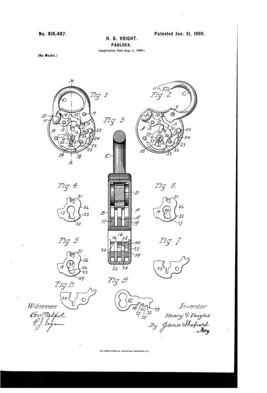
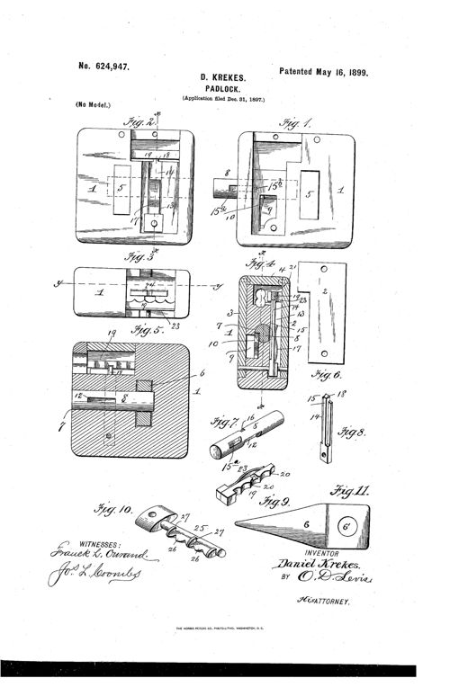
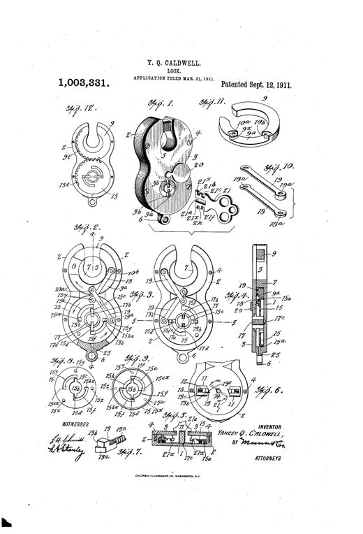
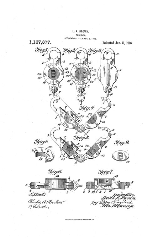
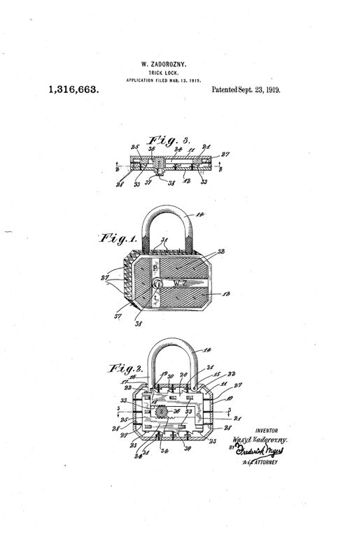
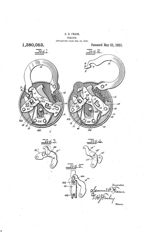
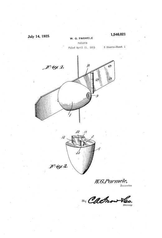
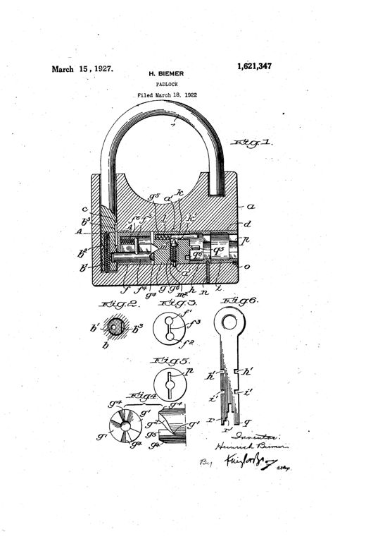
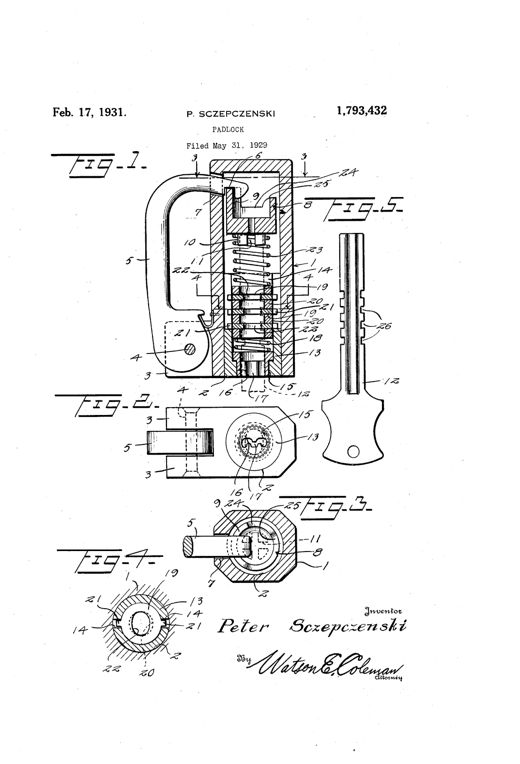
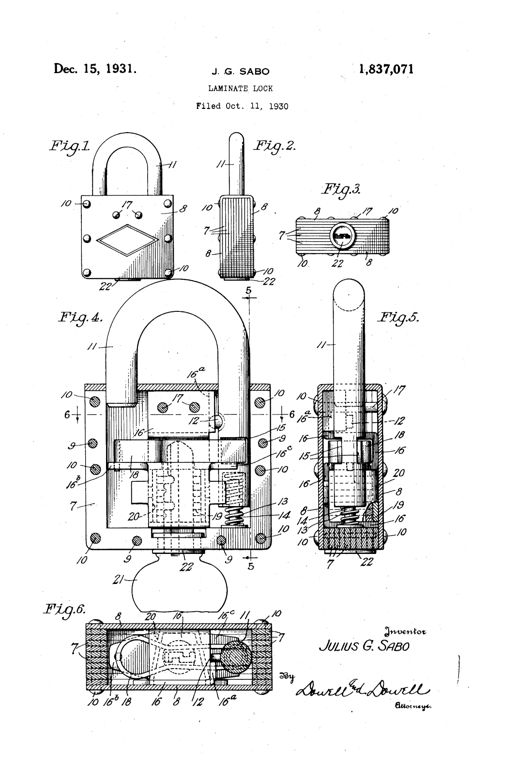
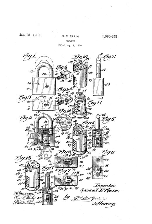
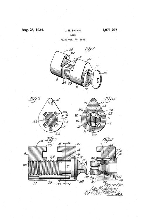
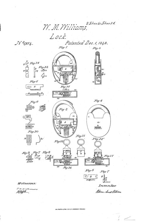
Patent drawing of a 19th-century padlock and door lock showing an internal toothed bolt rack, four spring-loaded sliding pieces in a rack box, a special multi-pin key, and adaptations to a rotary door lock and a liquor cask tap lock.LOCK AND KEYWilliam Morrett Williams · December 1, 1840Technical patent drawing showing nine figures of a padlock: an exterior view with U-shaped shackle and escutcheon, two cutaway interior views revealing internal hook and latch mechanisms, two individual hook pieces of differing weight, a latch piece, two keys with hollow bow handles, and a small bent spring trap.PADLOCKWilliam Ball · April 16, 1842Technical patent drawing showing three cutaway views of a padlock case with spring tumblers and a hidden safety bolt engaging a notched hasp, plus detail views of the bolt, bearings, and a double-bitted key.PADLOCK.George McGregor, Robert Lee, and Thos. G. Clinton · August 26, 1851Two front-view line drawings of a padlock, one showing the exterior with shackle labeled B, and one with the front plate removed revealing internal springs, levers, and a rotating disk mechanism, plus a small horizontal cross-section below.PADLOCKI. J. Oldis · January 1, 1856Patent drawing of a heart-shaped padlock shown in three cross-sectional views with shackle up and down, plus separate detail drawings of three tumblers, a bolt, a lever, and a barrel key.IMPROVEMENT IN PADLOCKSConrad Liebrich · August 11, 1863Patent drawing of a round padlock with a curved shackle, shown in exterior view, sectioned interior with divided stop-pins and a turning block, a separate flat key with two pins, and a rectangular door-lock variant with a similar pin mechanism.IMPROVEMENT IN LOCKS.Thomas George Harold · November 24, 1863Line drawing of a semicircular padlock shown in four views: an interior cutaway with the hinged two-part casing and spring-hook mechanism locked together, a side plan view, a vertical cross-section, and a fourth view showing the casing partially opened with its key.IMPROVEMENT IN PADLOCKSHenry D. Blake · August 15, 1865Patent drawing sheet showing seven numbered figures of a round padlock body with an oscillating bolt frame, notched sliders, a slotted flat key, and cross-sections revealing internal locking mechanism.IMPROVEMENT IN PADLOCKS, &c.Wilson Bohannan · August 6, 1867Patent drawing showing four views of a padlock's internal mechanism: three oval-shaped interior views (Figs. 1-3) revealing pivoted bolts, a coiled spring, and the shackle in various locked/unlocked positions, plus a fourth figure showing two separate curved bolt pieces labeled D and C with pivot holes and notches.IMPROVED PADLOCKWilliam Harvey · February 11, 1868Technical patent drawing of a heart-shaped padlock body with a curved shackle, hinged hasp, internal sliding bolts, springs, and a separate bit key, shown in nine labeled figures illustrating the lock's construction and operation.IMPROVEMENT IN PADLOCKSJacob E. Kohout · April 14, 1868Patent drawing sheet showing nine figures of a padlock's internal cylinder mechanism, shackle, tumblers, and a socket key, with lettered parts and an inventor's signature at bottom.IMPROVEMENT IN PADLOCKSFrank F. Landis · May 12, 1868Patent drawing sheet showing a heart-shaped padlock with a rounded shackle, internal cutaway views revealing the spring-loaded bolt and detent screw, and an elongated ridged key with a T-shaped handle.IMPROVEMENT IN PADLOCKSDavid F. Randall · July 14, 1868Cutaway drawing of a curved-frame padlock showing an internal spindle, sliding cup, cone, and pivoted catch bar, with a circular cross-section view below labeled with letters A through F.IMPROVEMENT IN PADLOCKSAmos S. Blake · November 17, 1868Patent drawing of a heart-shaped padlock showing its back plate, internal arc-shaped spring bolt, tumbler, hasp, and separate key, across ten labeled figures.PadlockAndy M. Adams · April 12, 1870Patent drawing sheet showing a round padlock mechanism in three states (locked, unlocked, hasp open), labeled internal parts including bolt C, dog D, rising-block E, and pinion F, alongside a bit key, individual component details, and two cutaway views of a trunk-lock variant with double hasps.IMPROVEMENT IN PAD AND TRUNK-LOCKSAndy M. Adams · November 8, 1870Patent drawing showing an oval padlock with a curved shackle, internal ring tumblers, a bolt mechanism, and an accompanying stepped key, presented in six labeled figures.IMPROVEMENT IN PADLOCKSJoseph Corbett · November 29, 1870Patent drawing of a padlock with rounded shackle labeled B, an internal oscillating tumbler with numbered sliders, a circular notched fence, a hooked lever, and a flat multi-bitted key, alongside a separate hasp piece and cross-section details.IMPROVEMENT IN PADLOCKSJohn H. Ames · January 17, 1871Patent drawing showing an oval padlock in six figures: two face views with the case cut away to reveal an internal hook-shaped bolt, pivoted tumbler, and sliding slotted plate, a cross-section showing the key channel, and three detail views of the bolt, plate, and tumbler components.IMPROVEMENT IN PADLOCKSGeorge Merkel and Charles H. Meyer · April 4, 1871Patent drawing sheet showing fifteen numbered figures of a heart-shaped padlock case, including cross-sections revealing stacked lever tumblers, a pivoted bolt, a U-shaped shackle with slotted prongs, and detail views of individual tumbler and bridge-plate components.IMPROVEMENT IN PADLOCKSSamuel W. Budd · January 23, 1872Patent drawing sheet showing six figures of a 19th-century padlock with a curved shackle arm, rotating face-plate with multiple key-holes, internal sliding bolt, tumbler, pinion and spring lever mechanisms, and a detachable key.IMPROVEMENT IN PADLOCKSDaniel Zeiler · February 27, 1872Patent drawing showing a round padlock with a J-shaped hooked staple, an interior view of the bolt mechanism, three variant sliding bolts, a cross-section of the case, the staple alone, and a separate key with a notched bit.IMPROVEMENT IN PADLOCKSHenry Essex · August 6, 1872Patent drawing of a padlock mechanism showing four figures: a circular lock case interior with pivoting lever tumblers and a curved hasp, a flat sliding key with a toothed bit, and a side view of a similar lock with an alternate curved tumbler arrangement.IMPROVEMENT IN PADLOCKS, &c.Daniel K. Miller · October 28, 1873Patent drawing of a round padlock showing its exterior with a curved shackle and hasp, plus two internal views revealing pivoted slotted tumblers and springs in locked and unlocked positions, alongside a flat key.IMPROVEMENT IN PADLOCKSFredrick Egge · December 23, 1873Patent drawing of a padlock showing eight labeled figures: interior views of the lock case with shackle open and closed, the spring-bolt with a stepped stud, pivoted tumblers, and a beveled-ward key.IMPROVEMENT IN PADLOCKSHerrmann Ahrend · January 27, 1874Patent drawing of a heart-shaped padlock interior mechanism alongside detailed views of a rotating key-hub and matching flat key with a bit-receiving slot.IMPROVEMENT IN PADLOCKSWilliam Wilcox · January 27, 1874Patent drawing of a round padlock showing six figures: the shackle and tumbler mechanism in locked and unlocked states, an exploded view of the lifted mechanism, a front elevation of the assembled lock, an edge view of the case, and a flat sheet-steel key shown from front and edge.IMPROVEMENT IN PADLOCKSFredrick Egge · July 14, 1874Patent drawing showing a padlock hasp with a hooked eye, a rounded rectangular case, and cross-sections revealing internal notched tumblers and pivoting dogs that lock the bolt in place.IMPROVEMENT IN PADLOCKS, &c.Daniel K. Miller · December 22, 1874Patent drawing of a heart-shaped padlock with an oval body, showing an internal spring, bolt, dog, tumblers, and a warded key, across ten labeled figures.IMPROVEMENT IN PADLOCKSBodo Wallmann · October 26, 1875Patent drawing showing a round padlock with a curved hasp, an internal circular spring bolt, and a series of small circular disk diagrams illustrating a rotating keyhole guard cap.IMPROVEMENT IN PADLOCKSGeorge R. Cutbirth · December 28, 1875Patent drawing sheet showing eleven figures of a cylindrical padlock, including exploded internal views with a rotating dust-cover plate, spring-loaded hook staple, tumbler mechanisms labeled E, and a bit key shown from side and end views.IMPROVEMENT IN PADLOCKSJacob L. Hirsch · January 4, 1876Two cutaway diagrams of a round padlock showing the internal bolt, tumblers, and spring mechanism with the shackle at top, alongside a drawing of the irregularly-shaped thrust key.IMPROVEMENT IN PADLOCKSIsrael Donald Boyer · April 25, 1876Patent drawing of a padlock showing the bow-shaped shackle, internal locking bolt with teeth, sliding plug, and a dovetail-mounted sliding guard covering the key-hole on the underside of the case.IMPROVEMENT IN KEY-HOLE GUARDSChristian Eisele · May 22, 1877Patent drawing of a U.S.-marked padlock showing exterior view, internal cross-section with bolt and tumblers, and a double-bitted key.IMPROVEMENT IN PADLOCKSWarren H. Taylor · July 10, 1877Patent drawing of a round padlock showing internal dog, tumblers, and pivoted shackle mechanisms across five figures, with a separate key illustration.IMPROVEMENT IN PADLOCKSFriend W. Smith and Fredrick Egge · September 4, 1877Patent drawing of a heart-shaped padlock showing the internal mechanism with a pivoted tumbler, hooked arm, sliding bolt, springs, and a key inserted into the keyhole, alongside separate detail views of the tumbler/pawl assembly and the bolt.IMPROVEMENT IN PADLOCKSJames J. Turner · December 4, 1877Patent drawing of a padlock with a curved shackle and round case, showing internal bolt, tumbler, and key mechanism in Fig. 1 and Fig. 2, with two small detail views (Fig. 3 and Fig. 4) of the tumbler component.IMPROVEMENT IN PADLOCKS.James J. Turner · December 25, 1877Three sectional elevation drawings of a padlock showing internal mechanism including a pivoted shackle, spring-loaded lock-bolt, swinging dog, and key pin, labeled with letters A through L across Figures 1, 2, and 3.IMPROVEMENT IN PADLOCKSWilliam P. Yoe · January 1, 1878Patent drawing of a tubular padlock showing a cylindrical lock case with a U-shaped shackle, internal cross-section revealing the bolt, spring, cam spindle and tumbler, plus separate detail views of the sliding clasp, spindle, tumbler, and a flat key with notched stem.IMPROVEMENT IN PADLOCKSHippolite A. Deraismes · March 5, 1878Patent drawing of a heart-shaped padlock case with a pivoted curved shackle, internal spring-loaded bolt and tumbler mechanism, and separate detail views of the tumbler and bolt components.IMPROVEMENT IN PADLOCKSWilson Bohannan · June 25, 1878Patent drawing of a padlock showing its rounded U-shaped shackle, internal bolt mechanism in cross-section, lock cover with a cross-shaped keyhole, and two distinct flat keys used to operate the locking bolts and an independent shackle-retaining bolt.IMPROVEMENT IN PADLOCKSLouis Hillebrand · July 23, 1878Patent drawing of an oval cast-iron padlock shown with its side plate removed, revealing a central shackle spindle surrounded by spring-loaded sliding tumblers, alongside separate views of the shackle and tumbler details.IMPROVEMENT IN PADLOCKSWilliam H. Bramble · July 30, 1878Patent drawing of a round padlock showing internal hooked dog, tumbler springs, and lettered parts, with a separate flat push key and cutaway views of the shackle open and closed.IMPROVEMENT IN PADLOCKS.Frederick Egge · August 27, 1878Patent drawing of a padlock showing cross-sections of the shell with tumblers, the U-shaped shackle with a lug, a locking-plate, key-tube, and an inverted view of the case.IMPROVEMENT IN PADLOCKSCharles W. A. Romer · March 18, 1879Patent drawing showing a padlock's oval case with U-shaped notched shackle, internal stacked latch plates with springs, and an ornate warded key.IMPROVEMENT IN PADLOCKSWilliam P. Wirth and Theodor H. Wichert · April 1, 1879Patent drawing of a padlock showing its rounded shackle and body in Figure 1 alongside a tapered screw-key, with internal cross-section views in Figures 2 and 3 revealing a row of sliding threaded tumblers and springs, and Figure 4 showing the lock's interior lever and bolt mechanism with the side plate removed.IMPROVEMENT IN PADLOCKSWilliam C. McGill · April 1, 1879Patent drawing of a cylindrical padlock with a heart-shaped hasp on the left, a key inserted into a raised chamber on top, and cutaway views below showing two interlocking sliding bolts with flanges and coiled springs.IMPROVEMENT IN PADLOCKSTheodor Heinrich Wichert · April 22, 1879Patent drawing showing a padlock's internal cross-latch mechanism, a U-shaped shackle, a warded key, and several small toothed latch pieces labeled with reference letters.IMPROVEMENT IN PADLOCKSWilliam P. Wirth and Theodor Heinrich Wichert · April 22, 1879Patent drawing of a hexagonal padlock showing internal bolt, tumbler, spring-trigger plate, curved operating arm, and a key with notched projections, alongside an exterior perspective view of the locked case with staple.Padlock.William F. Hofmann · July 29, 1879Patent drawing of a padlock showing its rounded shackle, tubular metal shell, and internal locking mechanism with lever tumblers, bolt, and springs in cross-section.IMPROVEMENT IN PADLOCKSWarren H. Taylor · August 5, 1879Patent drawing of a round padlock with a hinged hasp (Fig. 1), two enlarged cross-sections of the internal bolt and key mechanism (Figs. 2 and 3), and a perspective view of the notched key cylinder (Fig. 4).IMPROVEMENT IN PADLOCKSHenry A. Dodge · August 19, 1879Patent drawing of a padlock showing an internal rotating notched disk, gear segment, spring, anchor, and key mechanism in cross-section, with a shackle and a separate bent key illustrated below.IMPROVEMENT IN PADLOCKSConrad Jensen · September 30, 1879Technical patent drawing showing the circular internal mechanism of a padlock with a curved vibrating bolt, pivoted lever, spring-loaded blocking piece, and a separate key-post and tumbler piece, alongside a cross-section view showing a barrel key inserted into the lock.Padlock.Frank W. Mix · March 9, 1880Patent drawing of a padlock with the side wall removed, showing an arched shackle, two hooked dogs labeled C and D engaging catches on the shackle, a slotted plate-lever G, tumblers E and F, and a separate detail view of a bit key with a notched blade.PADLOCKElihu L. Perkins · April 11, 1882Patent drawing showing a metal hasp with a circular broken locking ring mounted at one end, plus detailed cross-sections of the internal spring-loaded locking pin and a key-operated padlock variant.HASP-LOCK.Byron D. West · February 19, 1884Patent drawing of a padlock showing five figures: cutaway side views of the lock body with shackle, spring bolt, and pivoted tumbler mechanism, plus a cross-sectional view of the key.PADLOCK.Wilson Bohannan · May 19, 1885Patent drawing of a padlock showing a curved metal shackle, internal notched tumblers, a pivoted dog, and a sliding bolt mechanism in cross-section, with separate detail views of the tumbler stack and key.PADLOCK.Milton Jackson · April 20, 1886Patent drawing of a padlock showing four figures: two face views of the lock body with shackle open and closed revealing internal bolt and tumbler mechanism, a cross-section with the key inserted, and a detached perspective of the tumbler piece.PADLOCK.Arthur Stewart · July 6, 1886Patent drawing showing a round padlock with a curved hasp in both locked and unlocked positions, an internal spring-actuated bolt and tumbler mechanism visible through a cutaway casing, a cross-sectional view of the lock body, and a separate illustration of the notched key with a round head and stepped tip.PADLOCK.Frank W. Mix · October 26, 1886Patent drawing sheets showing a padlock with a round hinged shackle, internal bolt and lever tumbler mechanism, and a key inserted into the case, with multiple cross-sectional and detail views labeled with reference letters.PADLOCKDavid Waine and Isaac Waine · April 10, 1888Patent drawing sheet showing twelve figures of a U-shaped shackle padlock, including exterior views, cross-sections revealing internal tumbler plates C and springs H, the key F, and a rotating guard plate L covering the keyhole.PADLOCK.William F. Troast · July 24, 1888Patent drawing of a round padlock with its face plate removed, showing an internal pivoted shackle, a hooked dog engaging tumbler notches, a detent-piece with an angled arm crossing the keyhole, and a stepped key with a notched shank labeled with numbered reference parts.PADLOCKWillard D. Doremus · May 7, 1889Patent drawing of a cylindrical padlock showing a cross-section with a U-shaped shackle, stacked internal tumbler plates labeled with letters, and several smaller diagrams of the individual tumblers, plates, and a bit key.PADLOCK.Jacob B. Amwake · October 29, 1889Patent drawing of a U-shaped shackle padlock showing internal spring-steel tumblers, a key inserted from below, and cross-sectional views labeled Fig. 1 through Fig. 8 with lettered parts such as A (case), B (shackle), C (tumblers), and F (key).PADLOCK.William F. Troast · December 31, 1889Patent drawing of a padlock showing the shackle, an internal eccentric dog and toothed tumbler mechanism, and a separate corrugated key with matching teeth.PADLOCK.Andrew S. Fisher · March 4, 1890Patent drawing sheet showing eight figures of a padlock: several face-on cutaway views of the lock body with numbered internal parts labeled with letters, a small ring-shaped tumbler guard, a tubular barrel key with a round handle, and a flat key variant, along with inventor's signature and witness signatures at bottom.PADLOCK.Frederick Egge · May 13, 1890Patent drawing of a padlock showing its curved shackle, internal pivoted tumblers with lugs and springs, and a flat stepped key used to release the mechanism.PADLOCKSamuel P. Stein · November 4, 1890Patent drawing of a padlock showing a U-shaped shackle, internal transverse bolt, springs, revoluble key-guide, and a barrel key with notched wards.PADLOCKJacob S. Peacock · May 26, 1891Patent drawing showing an oval metal lock case with a swinging multi-section locking dog engaging a two-shouldered bolt attached to chains, plus a small key and a padlock variant with a hook-shaped hasp.LOCK.Anson Parker Merrill · December 29, 1891Patent drawing of a padlock showing a U-shaped shackle inserted into a casing containing pivoted tumblers, sliding dogs, springs, and a twisted key mechanism, with seven labeled figures illustrating the internal parts and key.PADLOCK.Frederick W. Schultze · February 21, 1893Patent drawing of a round padlock with a curved shackle, shown in open and closed sections revealing internal ward posts, a rotating boss, and a hollow tubular key with a pivoted bit designed to fit only matching corrugations, alongside detail views of the key and lock mechanism parts.PADLOCKFranz Meinke · March 28, 1893Patent drawing of an 1894 padlock showing five figures: a cutaway shackle-and-casing assembly with numbered internal tumblers and springs, a perspective view of the internal locking frame with stacked notched tumblers, and a bottom plan view of the lock casing with keyhole and slot details.PADLOCK.Benjamin F. Loughmiller · April 10, 1894Patent drawing of a padlock with side plate removed showing internal shackle, spring-loaded tumblers, locking-dog, and key-locking bar, plus a separate key and locking-dog detail views.PADLOCKGeorge M. Hathaway · September 25, 1894Technical patent drawing showing exploded and sectional views of a padlock's internal casing, shackle, tumblers, dogs, catches, and a threaded key, with numbered reference lines identifying each part.PADLOCK.Ernst Wagenknecht · February 26, 1895Cross-section drawings of a padlock showing an arched hasp, internal pivoted tumblers, coil springs, and a multi-notched push key beside detailed tumbler and plate components.PADLOCK.Cornelius S. Van Wagoner · June 11, 1895An exploded and assembled set of technical patent drawings showing a ring-shaped padlock formed of two hinged semicircular jaws with interlocking spear-shaped heads, a sliding spring bolt, a keyhole, and a warded key, labeled with reference letters A through S.LOCK.Woodbury D. Roberts · September 29, 1896Patent drawing of a round padlock showing four figures: a perspective view with a hinged keyhole cover raised revealing internal pins and screws, a rear view with a pivoted back plate, a cross-sectional interior view with numbered mechanical parts including bolt, springs, and blocks, and an enlarged sectional diagram of the casing's internal layered components.PADLOCK.Theodor Grabowski, Kazimierz Jurkowski · February 16, 1897Patent drawing sheet showing ten figures of a padlock design, including exterior side views, internal mechanism with levers, catches, and springs, individual component plates, a locking-bar assembly, and a specially shaped key with cut-away shank.PADLOCKMartin H. Lutz and Morrow Moore · June 15, 1897Patent drawing of a padlock showing exterior view, internal bolt-and-tumbler mechanism with numbered parts, cross-sections, individual component details, and the setting key.PADLOCK.Warren H. Taylor · July 20, 1897Patent drawing of a circular padlock mechanism showing a rotary bolt, spring tumbler, pivoted dog, and hasp slot, with eight labeled cross-section and elevation figures.PADLOCK.Henry Roland · August 3, 1897Patent drawing of a round padlock showing two interlocking hinged jaws with internal tumbler mechanism, pivot-bolt, spring, and a flat key with notched wards.LOCKWoodbury D. Roberts · April 12, 1898Patent drawing of a padlock and cylinder lock cross-sections showing a shackle, tumbler-case, rotatable locking-bar, and numbered tumbler projections, with several keys and washers illustrated separately.LOCK.Ira J. Babcock · November 29, 1898Patent drawing of a padlock showing the case interior with pivoted shackle, swinging dog, three concentric tumblers, and a flat multi-winged key, alongside detail views of each tumbler and ward-plate.PADLOCK.Henry G. Voight · January 31, 1899Patent drawing sheet showing eleven figures of a hasp padlock, including side elevations, sections, and detail views of the bolt, retaining-bar, ward-plate, key, and staple, with numbered reference lines pointing to internal parts.PADLOCKDaniel Krekes · May 16, 1899Patent drawing sheet showing an exploded padlock with an arc-shaped shackle, circular actuator plate with teeth and slots, cam members, connecting links, and a multi-pronged key, alongside cross-sectional and detail views labeled with numbered reference lines.LOCKYancey Q. Caldwell · September 12, 1911Patent drawing of a Lewis A. Brown padlock showing two pivoted半-round members with an internal spring hook, shoulder, marked disk guard, and cross-sectional views labeled Figures 1 through 9.PADLOCKLewis A. Brown · January 11, 1916Three patent drawings of a padlock: an exterior perspective view marked 'WZ' with a keyhole, a vertical cross-section showing internal sliding bars, springs, and pins, and a horizontal cross-section showing the pinion and rack-toothed bars inside the casing.TRICK-LOCKWasyl Zadorozny · September 23, 1919Patent drawing of a round padlock showing internal tumbler mechanism, pivoted shackle, springs, and numbered parts across five figures, with the inventor's signature at the bottom.PADLOCKSamuel R. Fraim · May 31, 1921Patent drawing of an egg-shaped padlock housing shown applied to a hinged hasp with a staple, plus a cutaway longitudinal section revealing an internal spring-loaded tumbler, bolt, and key mechanism.PADLOCKWilliam Gordon Parmele · July 14, 1925Cutaway drawing of a padlock showing a rounded shackle, internal rotating lock cylinder with spring-loaded bolt, and a flat notched key beside smaller detail views of the crown, sleeves, and bore cross-sections.PADLOCKHeinrich Biemer · March 15, 1927Patent drawing of a cylindrical padlock with a pivoted shackle, showing internal spring-loaded tumbler, stacked guide plates, and a fluted key with transverse notches designed to align with the internal plates.PADLOCKPeter Sczepczenski · February 17, 1931Patent drawing sheet showing six figures of a laminated padlock: an assembled side view with shackle and rivets, an end view, a bottom view with keyhole, two cutaway sectional views revealing internal spring, shackle arms, and locking plate, and a plan section showing the key and internal guard mechanism.LAMINATE LOCKJulius G. Sabo · December 15, 1931Patent drawing sheet showing a padlock with a U-shaped shackle and rectangular body, alongside detailed exploded and sectional views of the internal disc-tumbler lock insert, casing, bolt, and key plug components labeled with numbered reference lines.PADLOCKSamuel R. Fraim · January 31, 1933Patent drawing of a cylindrical padlock mechanism showing the main lock-member with a threaded plug, key slot, spring tumblers, and a complemental screw-driven member with mating jaws, illustrated in perspective, cross-section, and detail views labeled Fig. 1 through Fig. 5.LOCKLyle B. Shinn · August 28, 1934