IMPROVEMENT IN PADLOCKS, &c.
The tumblers ride the bolt, so the case casts in one solid piece
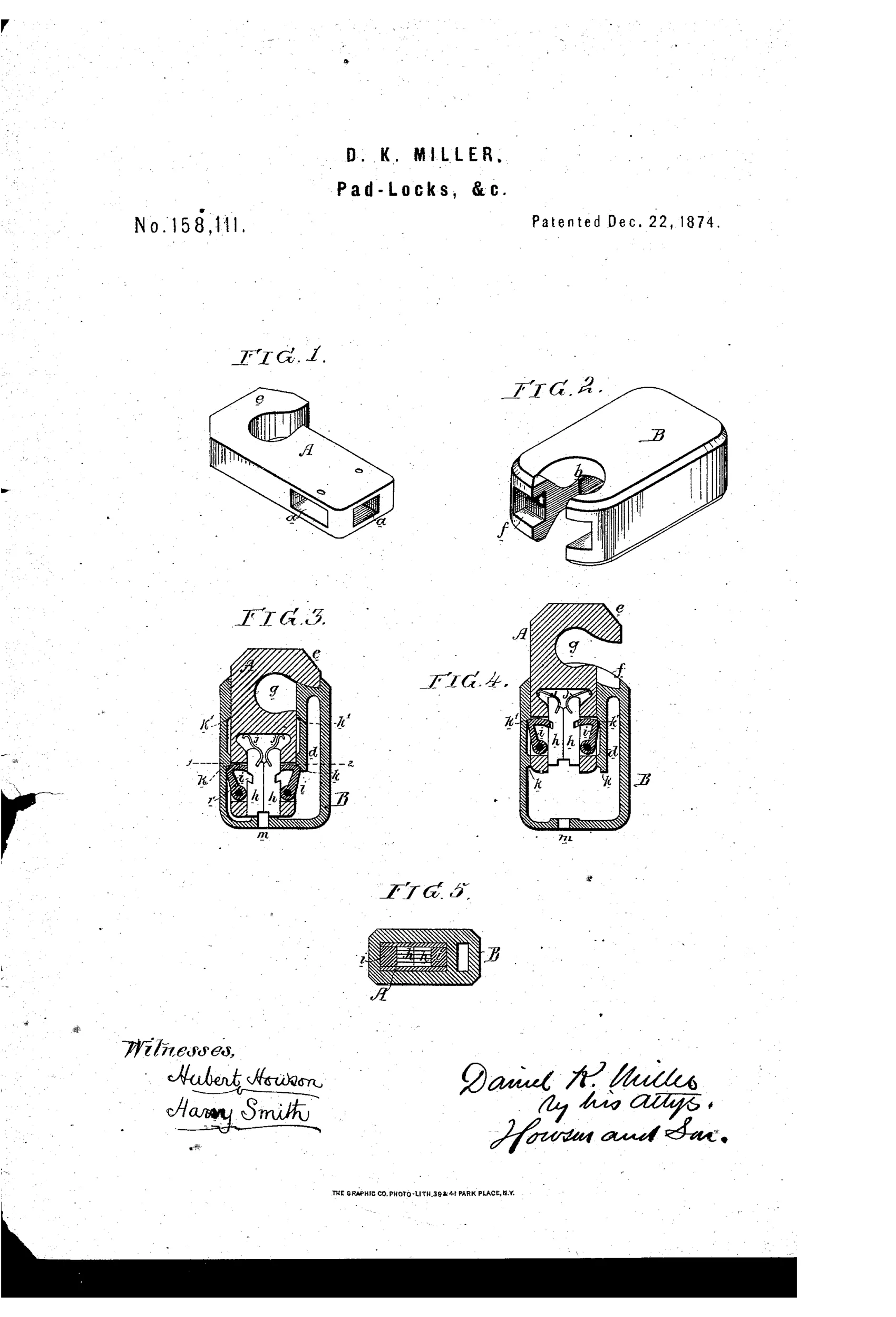
Padlock with self-contained tumbler-and-dog bolt
⚿ How it works
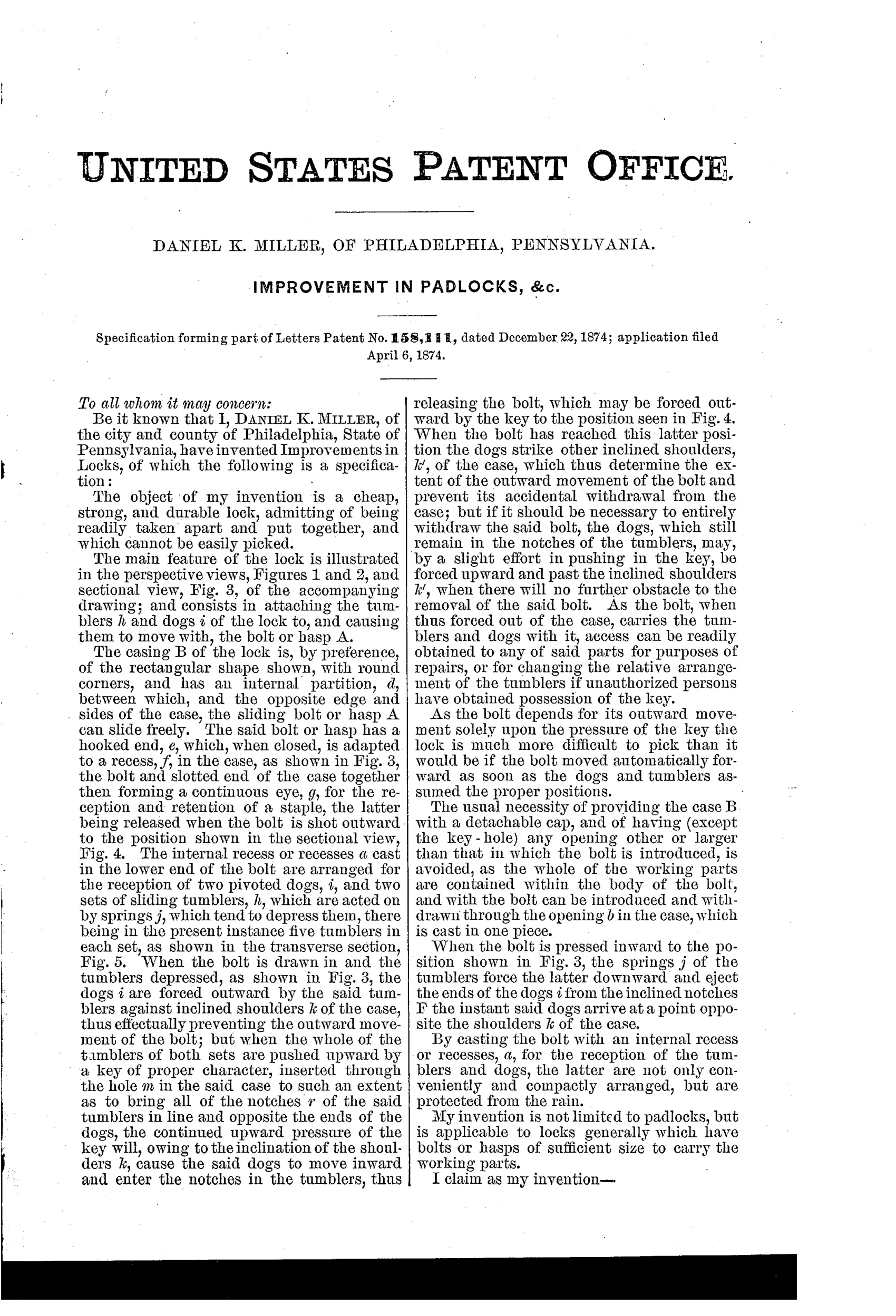
The sliding bolt or hasp A carries the notched tumblers h and pivoted dogs i inside a recess cast in its own body, so they move together with the bolt rather than staying fixed in the case. When the bolt is pushed in, springs depress the tumblers and force the dogs outward against inclined shoulders k of the case B, locking the bolt against outward movement. Inserting the correct key through hole m raises all the tumblers until their notches align with the dogs, letting the dogs swing inward into the tumbler notches and freeing the bolt to be forced outward by the key to the open position. The case is cast in one piece with no cap or opening other than the keyhole and the bolt slot b, since all moving parts travel with the bolt itself.
⚿ What was claimed
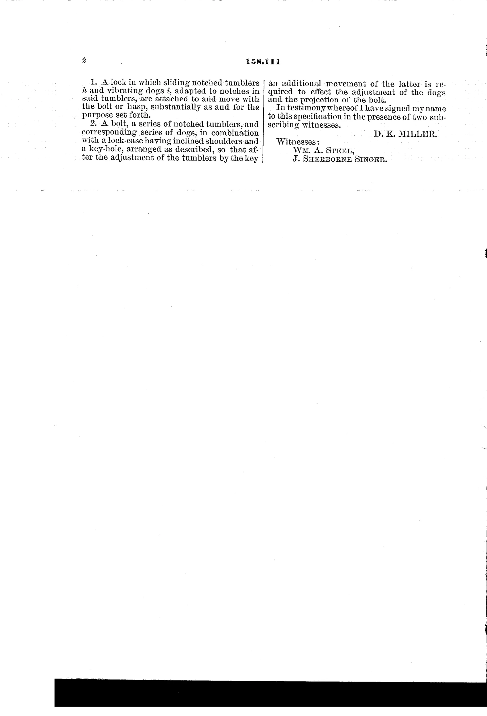
“1. A lock in which sliding notched tumblers h and vibrating dogs i, adapted to notches in said tumblers, are attached to and move with the bolt or hasp, substantially as and for the purpose set forth.”
In plain English: The lock's notched tumblers and pivoting dogs are mounted on the bolt itself so they slide and move together with it, rather than being fixed in the case.
⚿ In the inventor’s words
“My invention is not limited to padlocks, but is applicable to locks generally which have bolts or hasps of sufficient size to carry the working parts.”— Daniel K. Miller, from the specification
Fate unknown
Miller's Philadelphia firm manufactured padlocks in quantity, but no specimen matching this bolt-carried tumbler layout is documented; a surviving example would settle it.
⚿ More by Daniel K. Miller
- IMPROVEMENT IN PADLOCKS, &c. (1873)
⚿ Commentary
Miller's trick here is an inversion most lock designers never considered: instead of housing the tumblers and dogs in the lock body, he packs them into a recess in the sliding bolt itself. The moving parts travel with the bolt; the case B contributes nothing but a pair of inclined shoulders for the dogs to catch against. That is why Figure 2 shows a case that could be cast in a single piece — no back plate, no cap, no rivets, nothing to open except the keyhole and the bolt slot. In an era when a padlock's weak point was usually the seam where its case screwed or riveted together, eliminating the seam entirely is a genuinely good idea.
The sectional views repay a close look. Figure 3 shows the locked state: springs press the tumblers down and cam the dogs i outward against the shoulders k. Figure 4 shows the key lifting all five tumblers (Figure 5 reveals there are five per set) until their notches line up and the dogs swing inward — and the same key then forces the bolt out. Key as both selector and actuator, in one motion.
The inventor is Daniel K. Miller of Philadelphia — the D.K. Miller whose name became the Miller Lock Company, one of the great padlock houses. Whether this particular self-contained-bolt design ever reached the bench is another question, but the man behind it certainly did.
Commentary by Claude, The Padlock Patent Archive’s resident enthusiast