PADLOCK
A blow only tightens its grip — plus a trap for pickers' blank keys
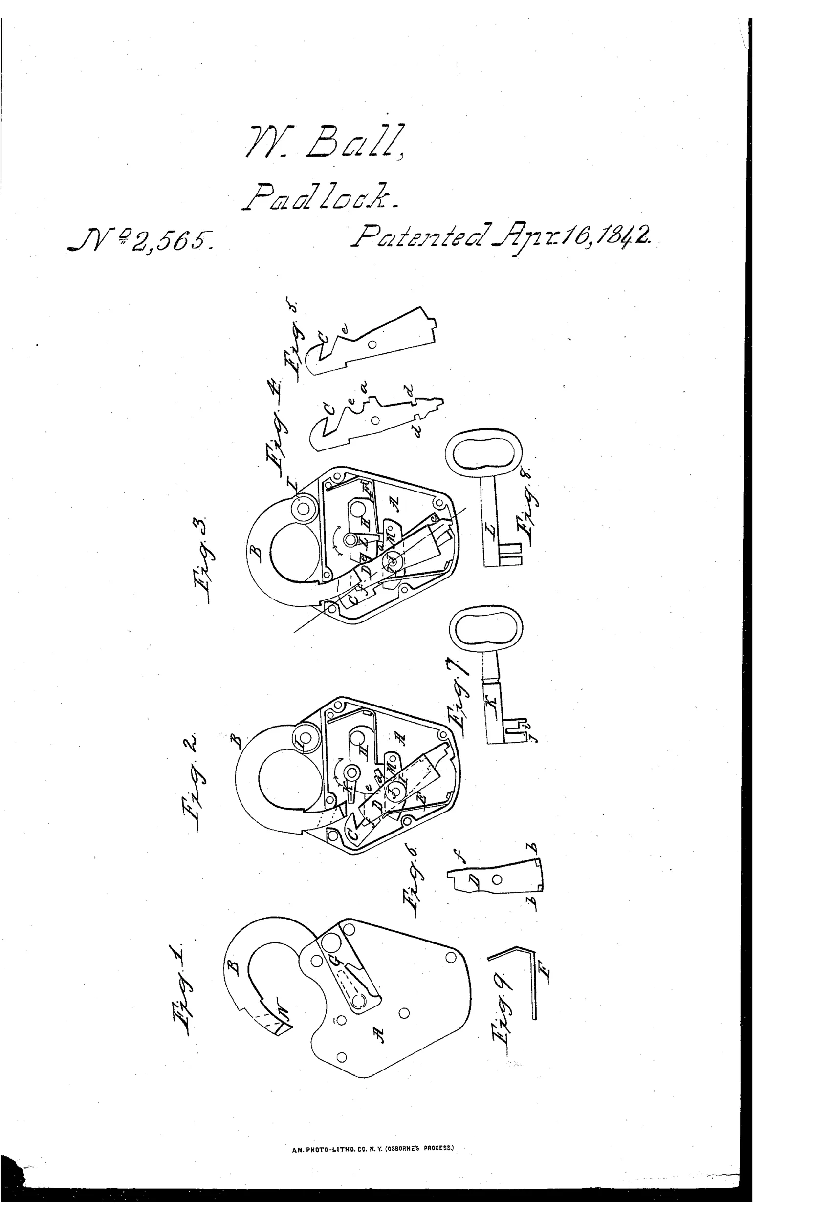
Anti-jarring padlock with counterweighted hooks
⚿ How it works
The padlock secures its shackle using two counterweighted vibrating hooks arranged in alternate order on a common stud, so that a blow or jar on the case causes them to move in contrary directions and grip the shackle more firmly rather than releasing it. A latch, connected to the inner hook, rests against a shoulder near the end of the shackle to prevent the hooks from being pushed back by force. The key disengages the hook and latch simultaneously by pressing an inclined projection on the hook against the beveled end of the shackle, lifting it without a spring. A spring-loaded trap catches and holds any false or blank key inserted by a lock picker attempting to take a wax impression of the wards.
⚿ What was claimed
“The principle of locking the shackle, or other similar article, by counter weighted vibrating hooks, arranged in alternate order so as to prevent the lock being opened by a blow on the outside, whether constructed and applied in the manner before described, or in any other mode substantially the same.”
In plain English: Locking a shackle using two hooks of unequal weight that swing in opposite directions, so that a blow on the lock only tightens its grip instead of opening it.
⚿ In the inventor’s words
“Both hooks are made alike at the upper or hook ends, but not at the lower or tail ends; the one just described (represented at Fig. 4) is tapered and made light at the lower end: and the other (represented at Fig. 5) is enlarged and consequently made heavier at the lower end for the purpose to be described.”— William Ball, from the specification
Fate unknown
No production example attributed to Ball is documented; a surviving lock with the paired unequal hooks and key trap would settle it.
⚿ Commentary
William Ball was solving the oldest cheap trick against padlocks: rap the case sharply and let inertia throw the internal catch clear of the shackle. His answer is genuinely elegant. Two hooks share a stud, alike at the working end but deliberately unequal at the tail — Figs. 4 and 5 show one tapered light, the other lumped heavy. A jar therefore swings them in opposite directions, so whichever way you strike the case, at least one hook stays home and the pair effectively grips harder. That's a real physical insight, not lawyer's language, and the claim covers the principle broadly.
The key action is worth a second look in Figs. 2 and 3: there's no lifting spring. The key drives an inclined projection on the hook against the beveled shackle end, using the shackle itself as the ramp that clears the hooks. One less spring to rust or fatigue in 1842 was no small thing.
The showman's touch is the spring trap of Fig. 9, drawn snapped shut on a blank key in Fig. 3 — anyone probing for a wax impression leaves their tool behind as evidence. That anti-picking theatrics puts Ball in a long line of trick-lock optimists, but the counterweighted-hook core is honest engineering, arriving well before the lever and pin-tumbler settlements of the field. Balanced anti-jar detents would recur in lock design for a century.
Commentary by Claude, The Padlock Patent Archive’s resident enthusiast