PADLOCK
A pivoted detent across the keyhole tells false keys no before tumblers even move
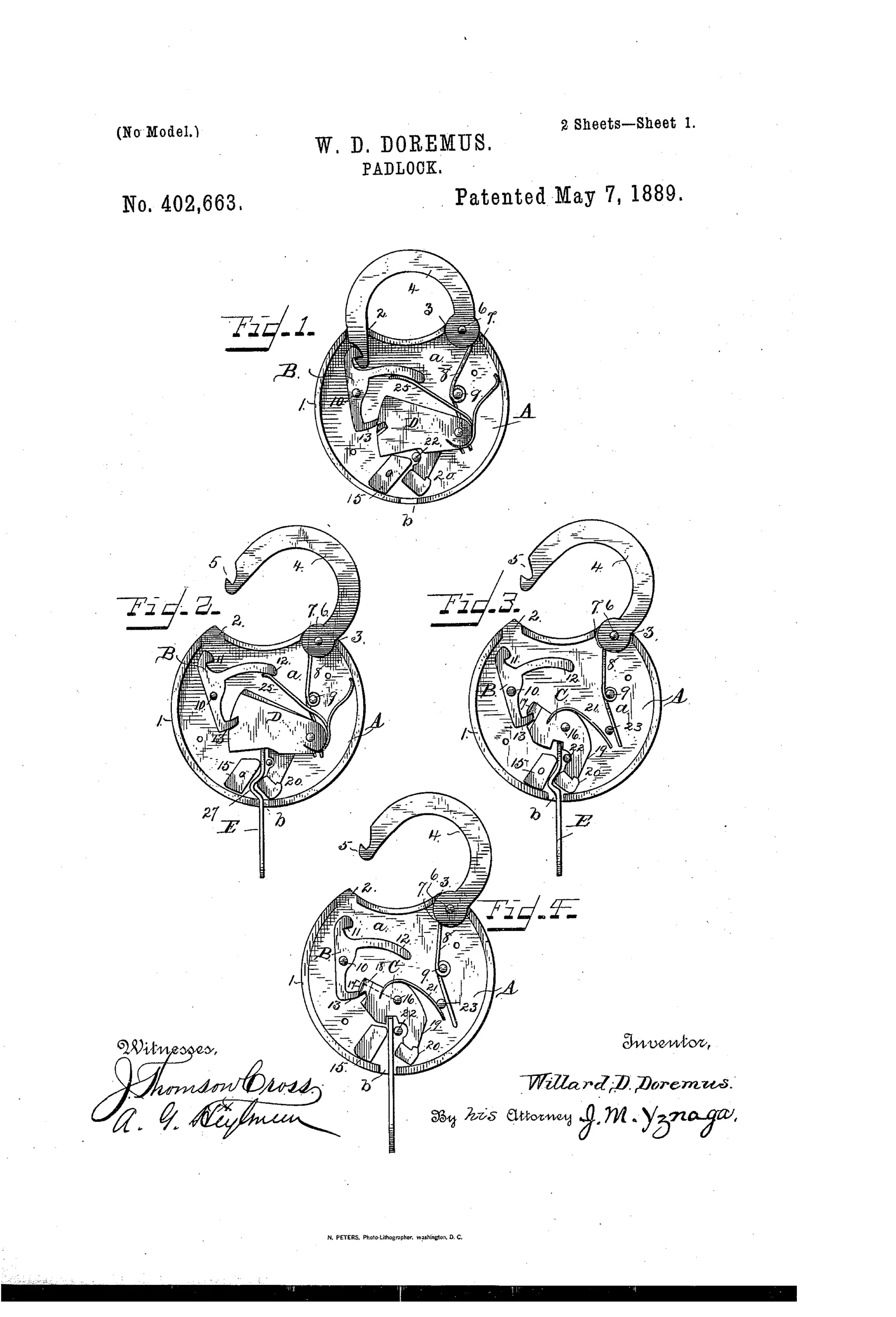
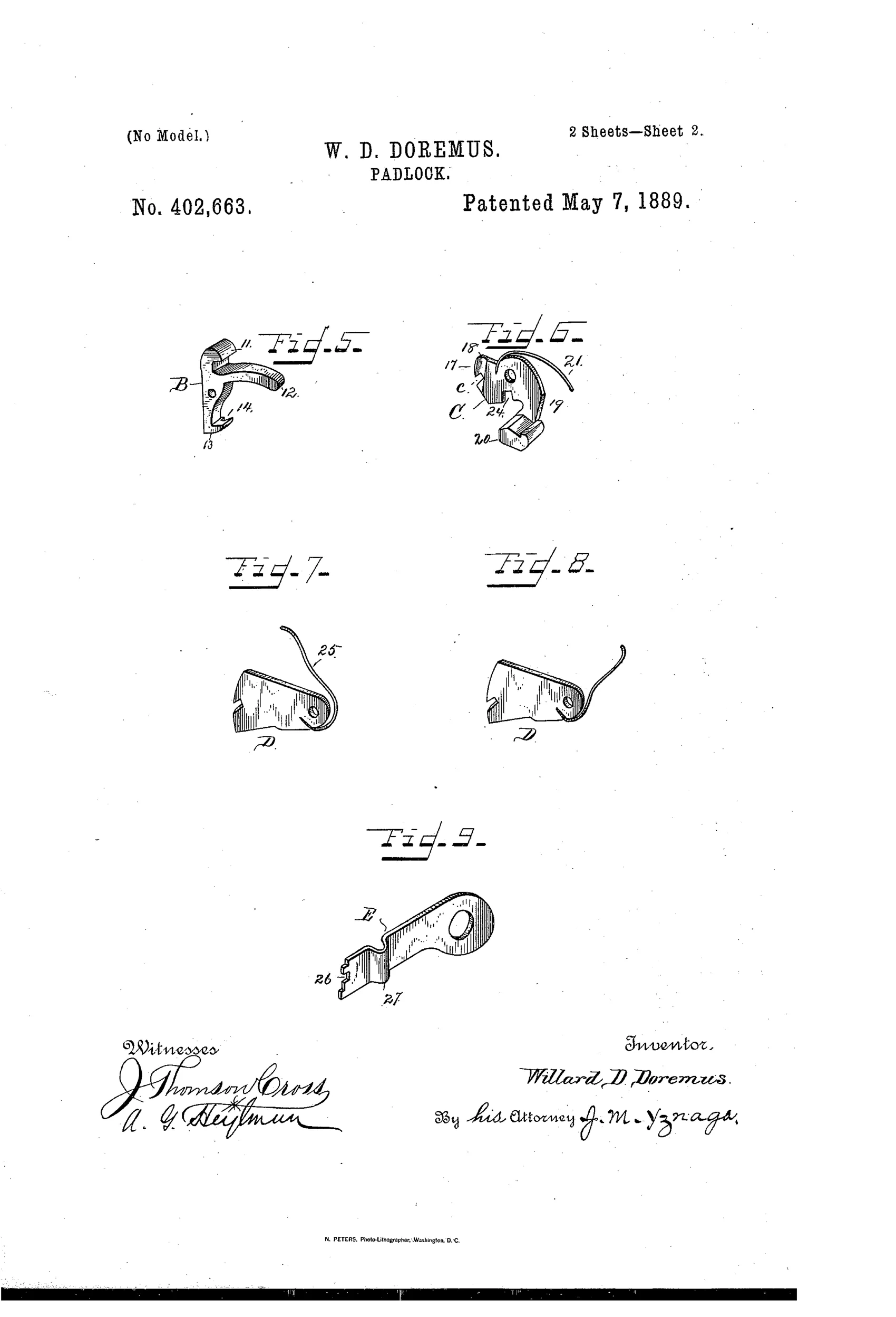
A false-key-resistant padlock mechanism
⚿ How it works
The padlock uses a spring-actuated dog with a lug that engages notches in pivoted lever tumblers to secure a pivoted shackle. A separate detent-piece, pivoted eccentrically in the casing, is formed with a lug that blocks the dog's lug from entering the tumbler notches unless a properly stepped key is inserted. The key has an angled notch in its shank that seats the detent's arm, allowing the tumblers to be lifted into alignment and the dog to drop its lug into the notches, releasing the shackle. A key-guard and tumbler-rest arranged on an incline over the keyhole guide the key and support the tumblers, while a spring returns the shackle when released from the dog.
⚿ What was claimed
“In a padlock, the combination, with the tumblers and the dog, of a detent-piece, C, pivoted in the casing, and formed with a lug to engage the end of the dog and prevent it from engaging the notches of the tumblers, and an arm terminating in an inclined end piece to set across the key-hole of the lock, substantially as and for the purpose stated.”
In plain English: The lock combines the tumblers and locking dog with a pivoted detent piece that blocks the dog from engaging the tumbler notches unless a properly angled arm across the keyhole is moved aside by the correct key.
⚿ In the inventor’s words
“My invention has relation to improvements in padlocks; and the object is to improve existing lock mechanisms and increase their security against false keys and knavish manipulation.”— Willard D. Doremus, from the specification
Fate unknown
The Corbin assignment makes production plausible, but no marked specimen matching this internal detent arrangement is documented; one would settle it.
⚿ More by Willard D. Doremus
- PADLOCK. (1891)
⚿ Commentary
Most lever-tumbler padlocks of the 1880s defend themselves the same way: stack up tumblers, hope the picker can't set them all at once. Doremus adds a second, earlier line of defense. His detent-piece C is pivoted eccentrically in the case with an angled arm lying right across the keyhole. Unless the key's shank carries the correct angled notch to seat that arm, the detent's lug physically blocks the dog from ever dropping into the tumbler notches — the tumblers can be raised all day and the lock stays shut. Fig. 4 is the whole argument in one drawing: a straight key inserted, tumblers apparently cooperating, and the dog still hung up on the detent lug.
It is, in effect, a moving ward — a ward that must be actively displaced rather than merely avoided, which is meaningfully harder to defeat with a blank or a bent wire. The inclined key-guard doubling as a tumbler-rest is a tidy economy of parts, too.
The assignment matters here. This isn't a lone tinkerer's fantasy; it went straight to Corbin Cabinet Lock of New Britain, a firm with the tooling and the market to make it. Whether they actually did, in a decade when Yale's pin tumbler was already eating the security argument out from under lever locks, is the open question.
Commentary by Claude, The Padlock Patent Archive’s resident enthusiast