PADLOCK
Stacked guide plates check the key's shape — wards masquerading as tumblers
Key-operated shackle padlock with anti-pick guide plates
⚿ How it works
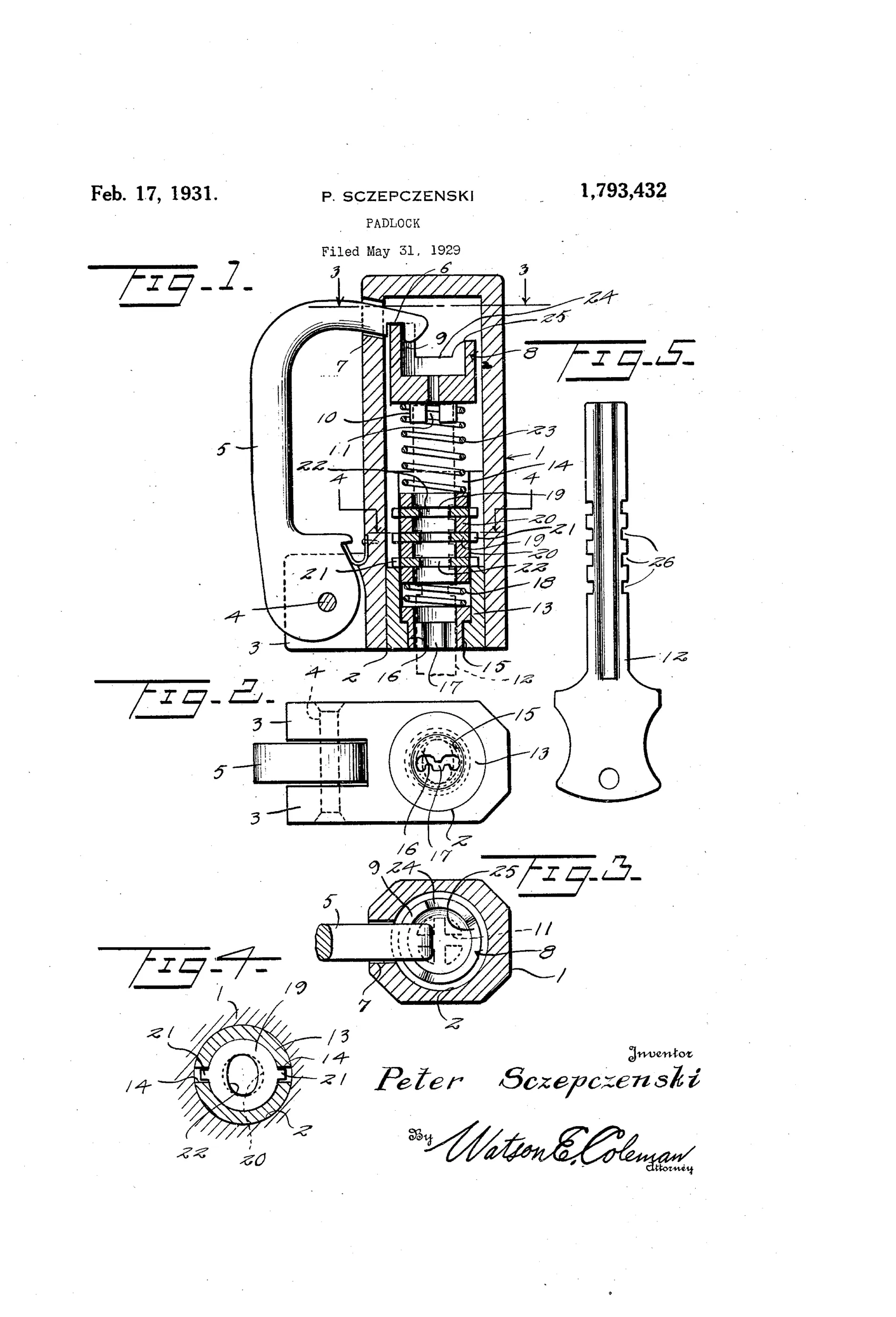
A pivoted shackle has an inturned, transversely slotted free end that extends through an aperture into a tubular shell body. A rotatable tumbler within the shell carries an arcuate finger that engages the shackle's slot when properly aligned, and is resiliently forced against the shackle by a coiled spring. A fixed cylinder with longitudinal slots houses stacked key-guide plates and spacing rings, each guide plate having an oval aperture and diametrically opposed ears that lock it against rotation. The operating key is longitudinally fluted with transverse notches spaced to match the guide plate apertures, so only a key with the correct notch spacing and width can pass through all the plates, engage the tumbler's crossed key slots, and rotate the tumbler to release or engage the shackle.
⚿ What was claimed
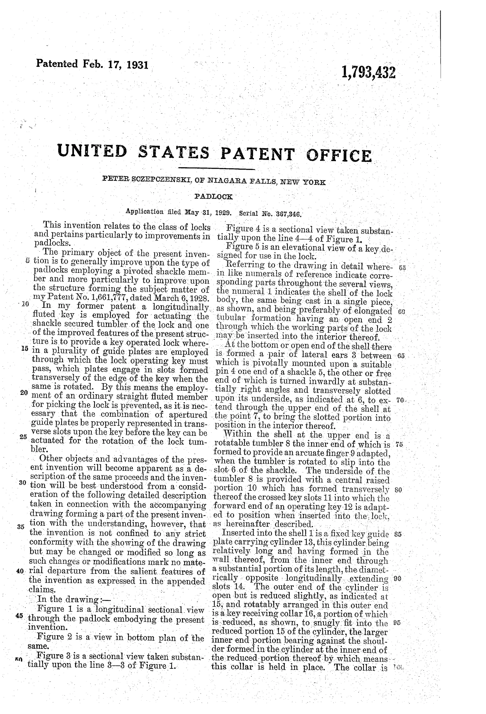
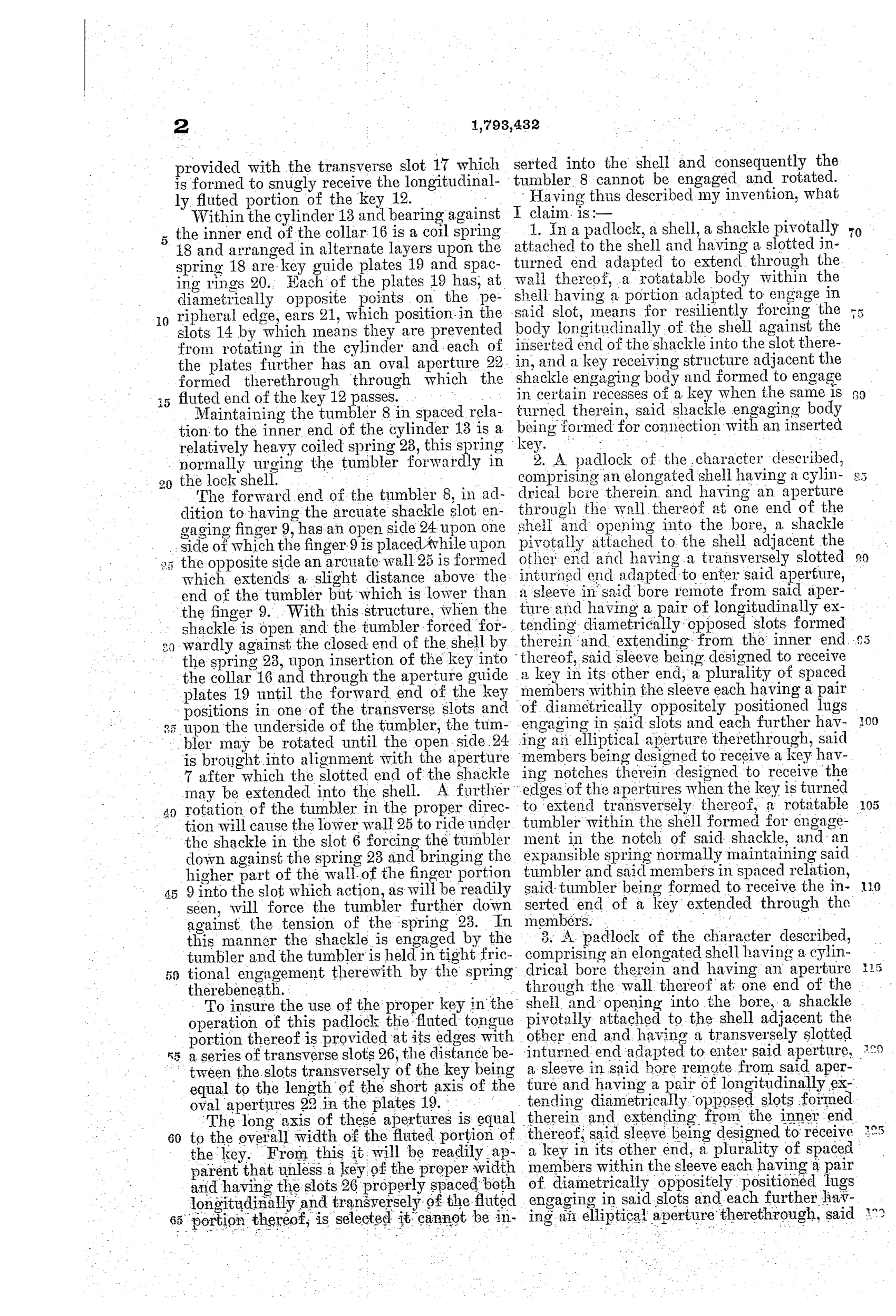
“1. In a padlock, a shell, a shackle pivotally attached to the shell and having a slotted inturned end adapted to extend through the wall thereof, a rotatable body within the shell having a portion adapted to engage in said slot, means for resiliently forcing the body longitudinally of the shell against the inserted end of the shackle into the slot therein, and a key receiving structure adjacent the shackle engaging body and formed to engage in certain recesses of a key when the same is turned therein, said shackle engaging body being formed for connection with an inserted key.”
In plain English: A padlock where a spring-loaded rotatable tumbler inside the shell engages a slotted shackle end, and is turned into place only by a key with matching recesses.
⚿ In the inventor’s words
“To insure the use of the proper key in the operation of this padlock the fluted tongue portion thereof is provided at its edges with a series of transverse slots 26, the distance between the slots transversely of the key being equal to the length of the short axis of the oval apertures 22 in the plates 19.”— Peter Sczepczenski, from the specification
Fate unknown
No production example or manufacturer connection is documented for this independent Niagara Falls inventor; a surviving lock with its distinctive fluted, notched key would settle it.
⚿ Commentary
Sczepczenski's padlock reads at first like a pin-tumbler competitor, but look at what actually does the work. The shackle is held by a single spring-loaded rotating tumbler with an arcuate finger dropping into a slot on the shackle's inturned end. Everything else in that busy Fig. 1 section — the stacked plates 19, the spacing rings, the oval apertures with locking ears — exists only to verify the key's silhouette. The fluted key of Fig. 5, with its transverse edge notches spaced to match the plate apertures, must thread the whole stack before it can reach and turn the tumbler.
That is warding, elaborated. Nothing in the stack moves in response to the key; the plates are a fixed obstacle course. A lockmaker in 1860 would recognize the principle instantly, and a picker would recognize the weakness: any slim tool that clears the ovals and engages the crossed key slots on the tumbler defeats it, regardless of notch spacing. Yale had settled this argument sixty years earlier — moving detainers beat fixed obstructions.
Still, there is honest craft here. The spring forcing the tumbler axially against the shackle slot gives positive engagement without a separate bolt, and the whole lock assembles as a tube of stacked parts — cheap to build in theory. It is a workmanlike dead end: a 1929 refinement of a pre-1860 idea, filed just as the pin-tumbler padlock was becoming the universal answer.
Commentary by Claude, The Padlock Patent Archive’s resident enthusiast