LAMINATE LOCK
Slaymaker stacks its case from U-plates, six years after Soref showed the way
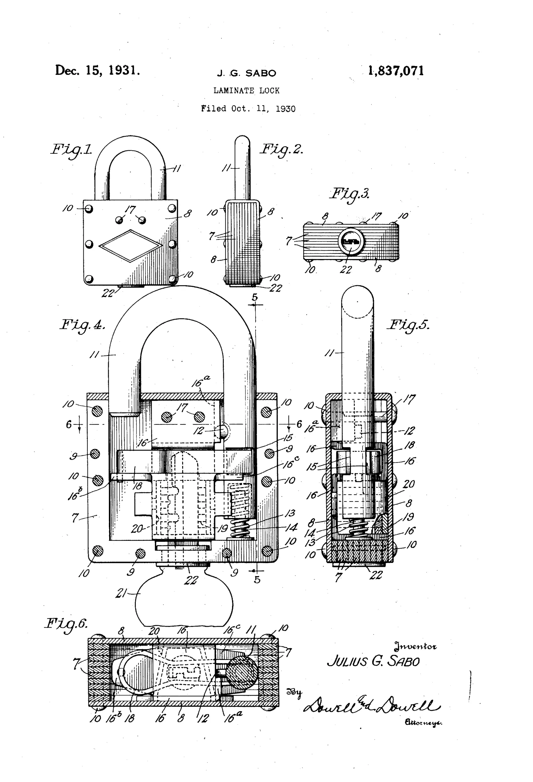
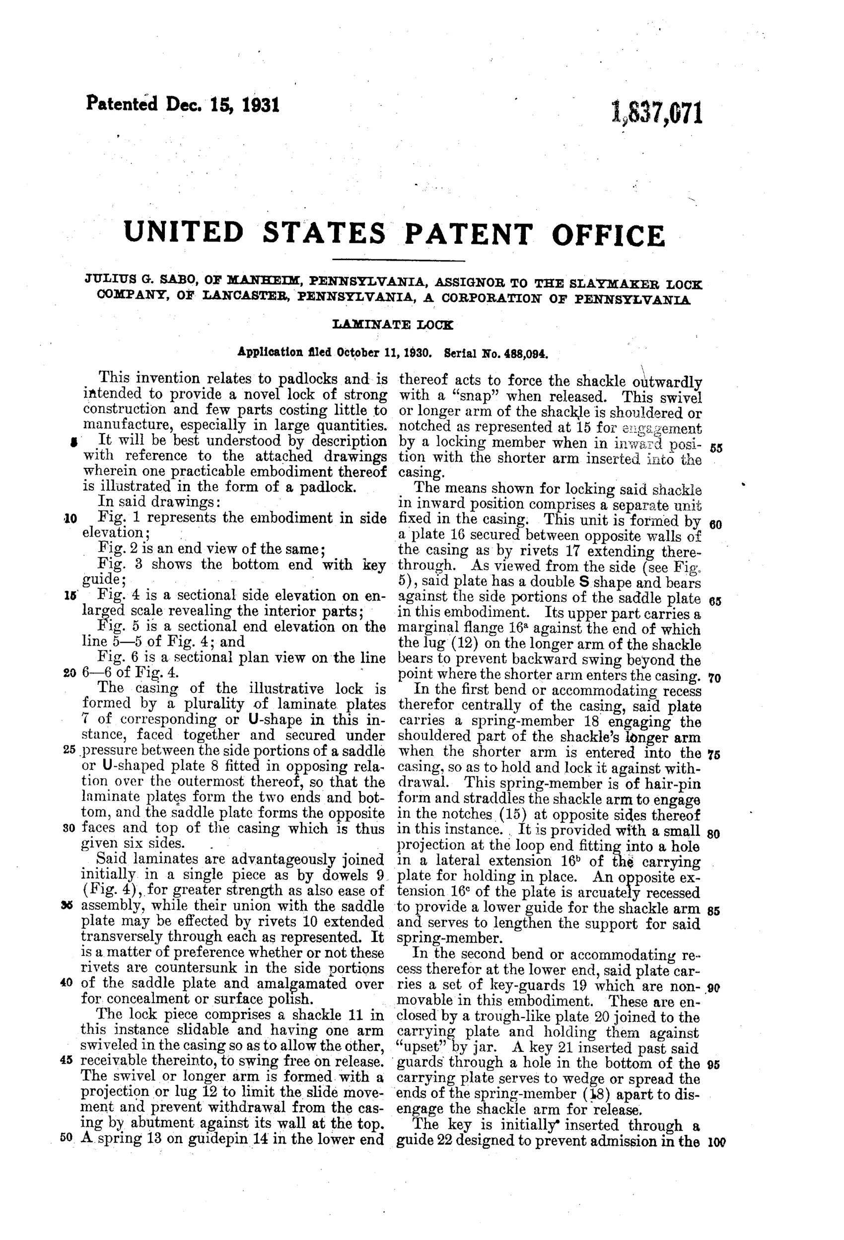
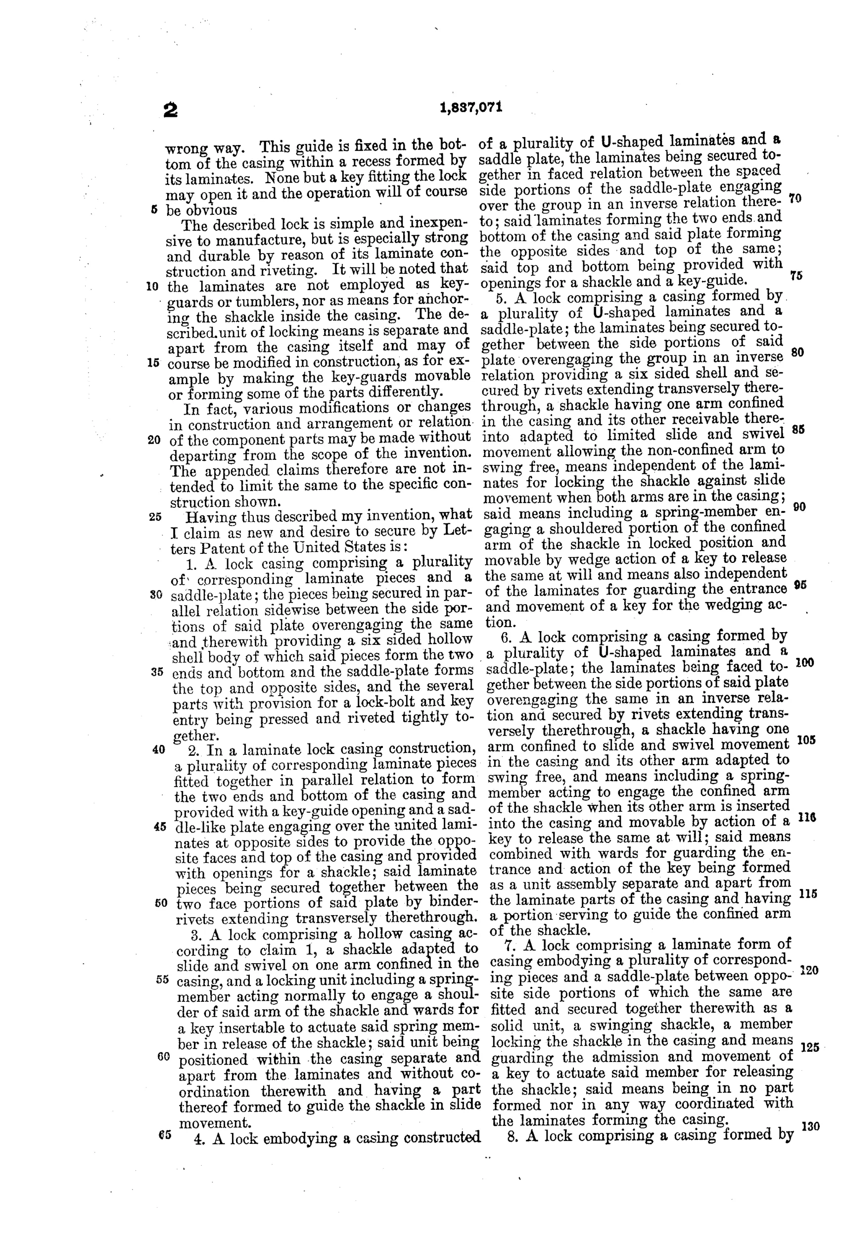
A padlock with laminated plate casing construction
⚿ How it works
The lock casing is built from a plurality of U-shaped laminate plates faced together and secured under pressure between the side portions of a saddle plate, forming a six-sided hollow shell. The shackle has one arm confined to slide and swivel movement in the casing while the other arm swings free and can be inserted for locking. A hairpin-form spring member engages notches on the shackle's longer arm to lock it against withdrawal, and this spring is released by wedging action when a properly fitted key is inserted through guarded wards. Key-guards and a key-guide opening, formed separate from the laminates, prevent improper key insertion and protect the release mechanism.
⚿ What was claimed
“A lock casing comprising a plurality of corresponding laminate pieces and a saddle-plate; the pieces being secured in parallel relation sidewise between the side portions of said plate overengaging the same and therewith providing a six sided hollow shell body of which said pieces form the two ends and bottom and the saddle-plate forms the top and opposite sides, and the several parts with provision for a lock-bolt and key entry being pressed and riveted tightly together.”
In plain English: The lock's casing is made by stacking several identical U-shaped metal plates and clamping them together with a saddle-shaped cover plate to form a strong six-sided hollow shell, with openings left for the bolt and key, all riveted tightly together.
⚿ In the inventor’s words
“None but a key fitting the lock may open it and the operation will of course be obvious”— Julius G. Sabo, from the specification
Manufactured and sold
Slaymaker produced laminated padlocks in quantity through the 1930s, and this assigned patent underpins that line; surviving Slaymaker laminated locks match this construction.
⚿ Commentary
By 1930 the laminated padlock was no longer a novelty — Harry Soref had built Master Lock on the idea in the mid-1920s, stacking stamped plates and riveting them into a body that shrugged off hammers and bolt cutters far better than the thin stamped shells it replaced. What Sabo does here, on behalf of Slaymaker of Lancaster, is find a patentable variation: instead of flat plates stacked face to face through the whole body, he uses U-shaped laminates clamped inside a wrap-around saddle plate that forms the top and both sides. The claim is really about that saddle — it turns the laminate stack into a captive core rather than the whole wall.
The internal works are deliberately cheap and simple. Fig. 4 shows a hairpin spring biting into notches on the long shackle leg; the key doesn't turn tumblers so much as wedge the spring legs apart. The security lives almost entirely in the warded key-guide at the bottom (Fig. 3), which is the weak point — warding was already an antique defense by 1931.
So this is a manufacturing patent, not a security patent. Its real subject is riveting pressure, stamping dies, and how few operations it takes to build a padlock body. That was exactly the game every big maker was playing during the Depression, and Slaymaker played it well.
Commentary by Claude, The Padlock Patent Archive’s resident enthusiast