PADLOCK.
Two secret moves before the key even touches the keyhole
Padlock with concealed, disguised keyhole entrance
⚿ How it works
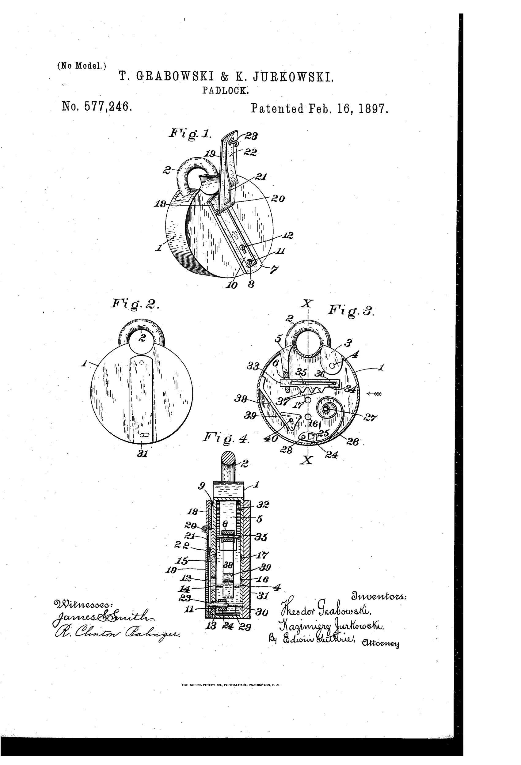
The padlock's casing has a hinged, spring-loaded keyhole-cover concealing the true keyhole, secured by a pin-hook engaging a pivoted block on the back plate. Operating an outer pivoted plate on the back moves the block and releases the hook, allowing the cover to spring open and reveal a sliding keyhole-plate. This plate must then be slid to align its second keyhole with the true keyhole in the casing before the key can reach the bolt; a false keyhole nearby merely actuates a spring-loaded triangular block that clicks but does nothing. Only by performing both secret movements in sequence can the true keyhole be exposed and the bolt, which engages a slotted pivoted bow, be operated by the key.
⚿ What was claimed
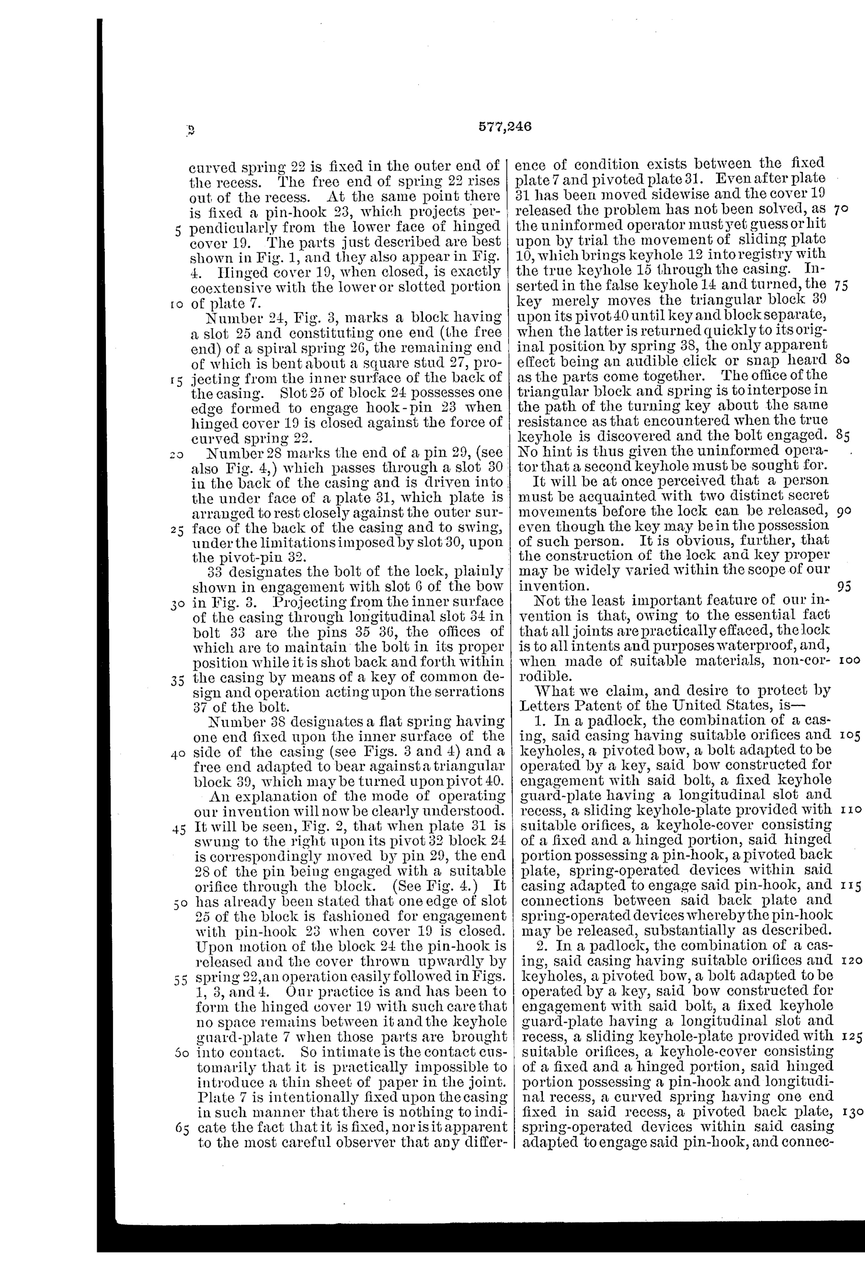
“In a padlock, the combination of a casing, said casing having suitable orifices and keyholes, a pivoted bow, a bolt adapted to be operated by a key, said bow constructed for engagement with said bolt, a fixed keyhole guard-plate having a longitudinal slot and recess, a sliding keyhole-plate provided with suitable orifices, a keyhole-cover consisting of a fixed and a hinged portion, said hinged portion possessing a pin-hook, a pivoted back plate, spring-operated devices within said casing adapted to engage said pin-hook, and connections between said back plate and spring-operated devices whereby the pin-hook may be released, substantially as described.”
In plain English: The padlock combines a casing, a pivoted bow-bolt mechanism, a fixed guard-plate, a sliding keyhole-plate, a hinged keyhole cover with a hook, and a pivoted back plate with springs, all connected so that moving the back plate releases the cover to expose the real keyhole.
⚿ In the inventor’s words
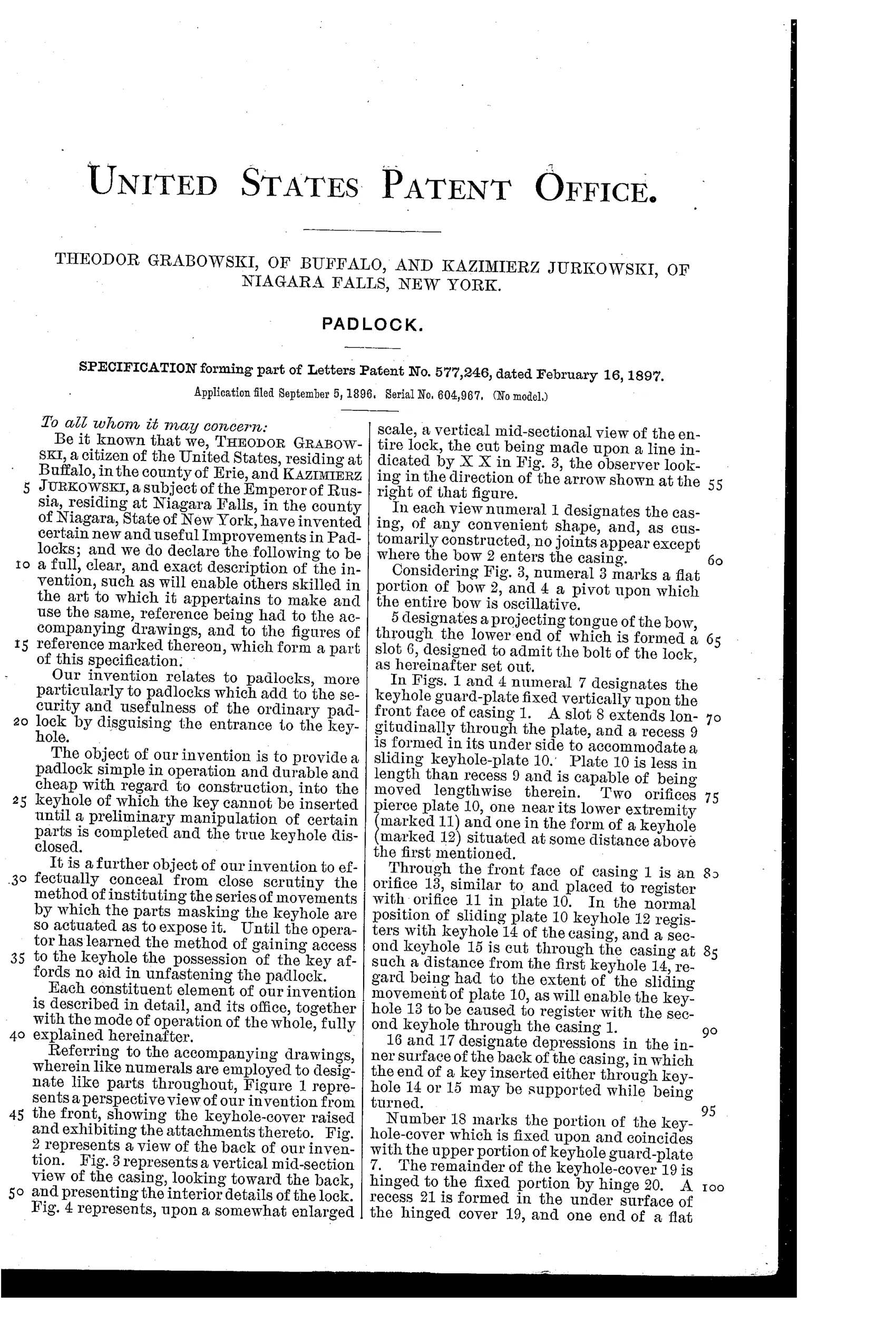
“The object of our invention is to provide a padlock simple in operation and durable and cheap with regard to construction, into the keyhole of which the key cannot be inserted until a preliminary manipulation of certain parts is instituted and the true keyhole disclosed.”— Theodor Grabowski, Kazimierz Jurkowski, from the specification
Fate unknown
No production example of this hidden-keyhole design is documented; a surviving marked specimen matching the drawings would settle it.
⚿ Commentary
Grabowski and Jurkowski's contribution to the trick-lock tradition is a padlock that treats the keyhole itself as the thing to be locked. A hinged spring cover hides the real keyhole and is held shut by a pin-hook; you release it by shifting a pivoted plate on the back of the case. Even then you are not done — a sliding keyhole-plate must be pushed into alignment before the key can pass through to the bolt. And in a nice bit of malice, there is a decoy keyhole nearby wired to a spring-loaded triangular block that clicks convincingly and does absolutely nothing.
That false keyhole is the detail worth lingering on in Fig. 3. It shows the inventors thinking like their adversary: a picker probing the visible opening gets tactile feedback — resistance, a click — that suggests progress. It is an early example of designed-in misdirection rather than mere concealment.
The actual bolt-and-bow work behind all this theater is ordinary, and the layered construction visible in Fig. 4 — guard-plate, sliding plate, hinged cover, back plate, plus their springs and connections — is a lot of fitted parts for a lock whose security still depends on the secret staying secret. Once the sequence is known, it is just a warded padlock with a two-step preamble. Charming, sincere, and squarely a dead end against the pin-tumbler tide already rising by 1897.
Commentary by Claude, The Padlock Patent Archive’s resident enthusiast