PADLOCK
A Fraim of Lancaster drops the whole lock in as one cartridge
A disc-tumbler padlock with removable lock insert
⚿ How it works
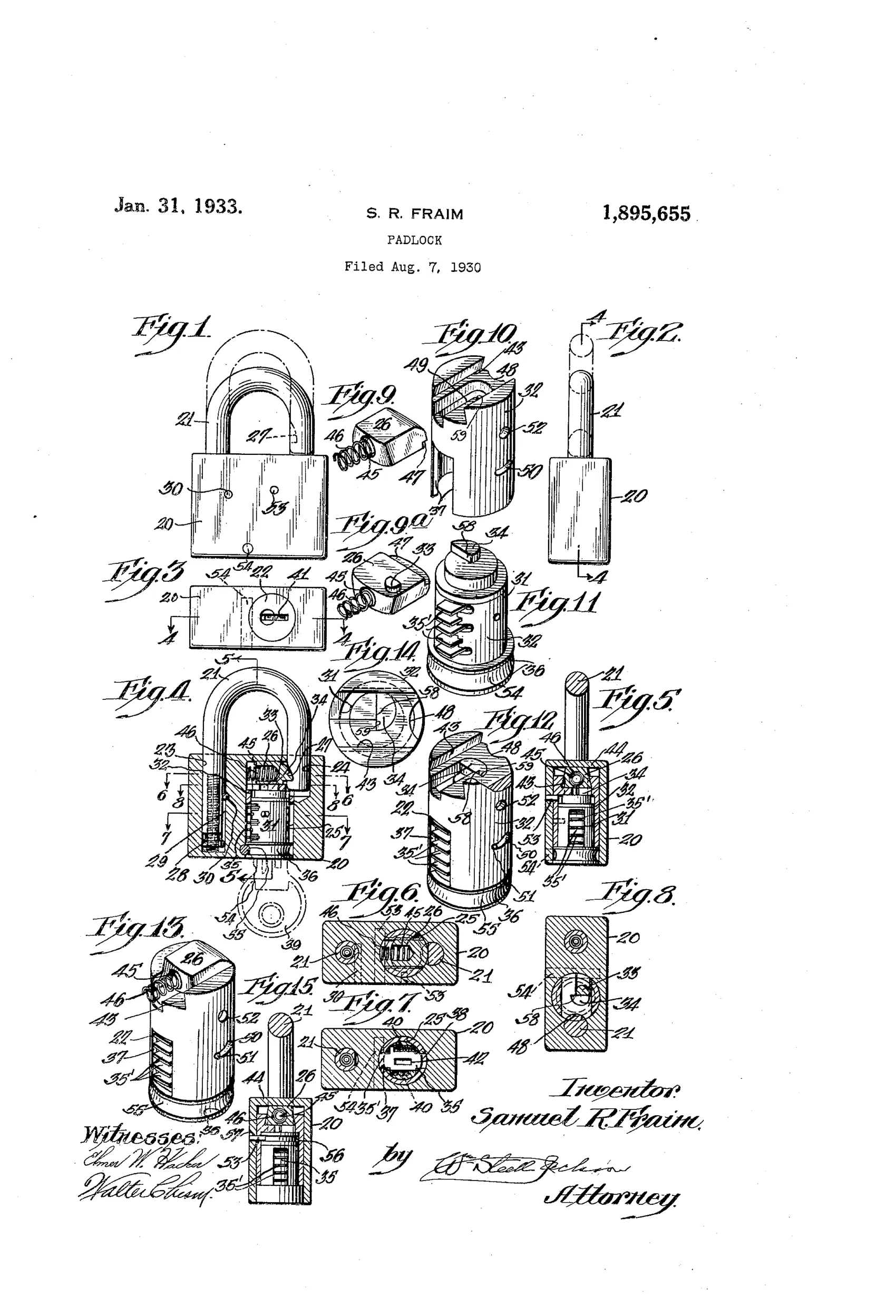
The padlock body is a short section cut from a solid bar, bored from one end to receive the shackle legs and from the other end to receive a preassembled lock insert unit. The insert comprises an inner barrel carrying spring-pressed disc tumblers, an outer shell or sleeve surrounding the barrel, and a spring-pressed bolt mounted transversely at the top of the sleeve with a downward dog engaging a cam on the barrel. Inserting the correct key retracts the disc tumblers flush with the barrel, allowing the barrel to rotate within the sleeve, which via the cam and dog withdraws the bolt from the shackle notch to release the shackle. The entire lock insert is assembled as a self-contained unit before being slid into the straight cylindrical bore of the padlock body, simplifying manufacture.
⚿ What was claimed
“A padlock including a shackle, a body mounting the shackle at one end and having a straight cylindrical bore from the other end and an insert within the bore comprising a transverse bolt, an outer casing mounting and guiding the bolt and a disc tumbler key plug inside the casing adapted to be turned with respect to the casing when a suitable key has been inserted in the plug.”
In plain English: The padlock has a body with a straight bore into which a complete pre-assembled lock unit is inserted, consisting of an outer casing holding a spring-loaded bolt and an inner disc-tumbler key plug that turns to move the bolt when the right key is used.
⚿ In the inventor’s words
“One purpose of my invention is to facilitate padlock manufacture by formation of the padlock body from a solid block and separate assembly of the complete locking mechanism for inclusion within it.”— Samuel R. Fraim, from the specification
Fate unknown
Fraim manufactured disc-tumbler padlocks in quantity, but I cannot confirm this specific insert construction reached production; sectioning a period Fraim cylinder padlock would settle it.
⚿ More by Samuel R. Fraim
- PADLOCK (1921)
⚿ Commentary
Samuel R. Fraim of Lancaster, Pennsylvania — the family behind the E. T. Fraim Lock Company, one of the busiest padlock houses in the country — is not chasing pick resistance here. He is chasing the assembly line. The whole point, stated plainly in the specification, is that the padlock body is just a slice of solid bar stock with two straight bores: one for the shackle legs, one for a complete, pre-assembled lock unit that slides in like a cartridge. Every fiddly part — disc tumblers, spring bolt, cam — is built up on the bench as a self-contained module before it ever meets the case.
The drawing sheet rewards a close look. Figures 9 through 14 are essentially an exploded manufacturing diagram: the transverse bolt riding in the top of the outer sleeve (Fig. 10), the disc-tumbler plug with its spring-pressed wafers (Fig. 11), and the assembled insert in Fig. 12 ready to be pushed home. The dog-and-cam linkage that translates plug rotation into bolt withdrawal is the only mechanism of consequence, and it is entirely conventional — deliberately so.
This is where padlock patenting had arrived by 1930: the tumbler wars were over, disc and pin cylinders had won, and the remaining battleground was cost per unit. Fraim's insert idea is the same logic that gave us the replaceable-core padlock. A workmanlike patent, but from a firm that knew exactly what a padlock cost to make.
Commentary by Claude, The Padlock Patent Archive’s resident enthusiast