The Padlock Patent Archive

Three centuries of keeping things shut

Shackle

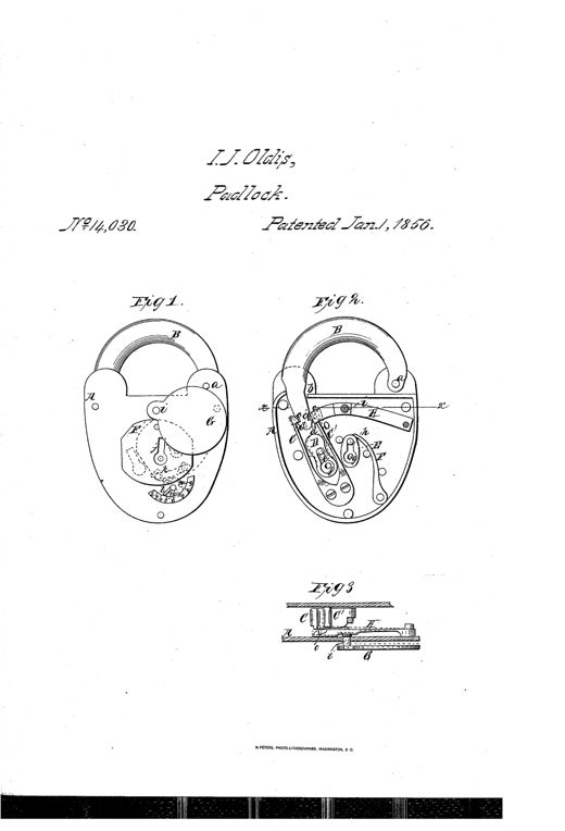
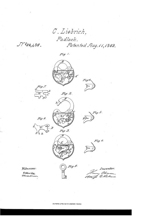
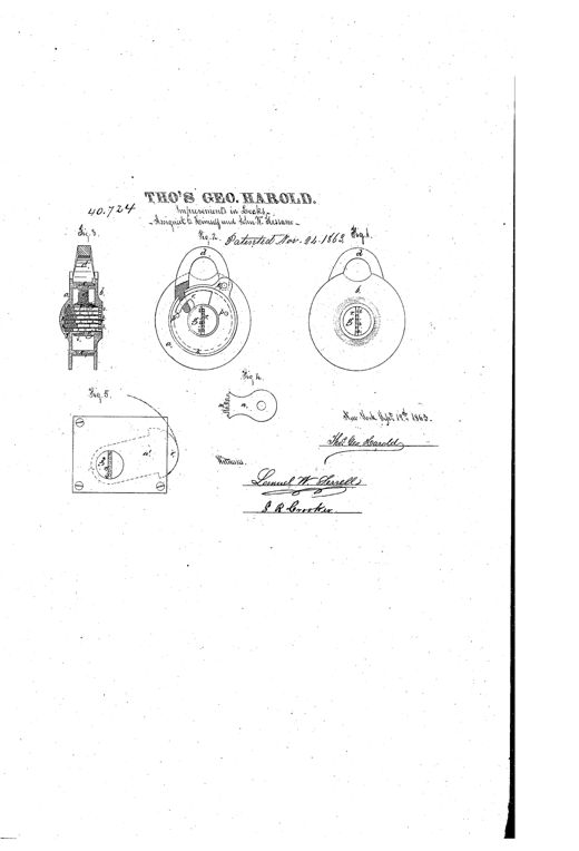
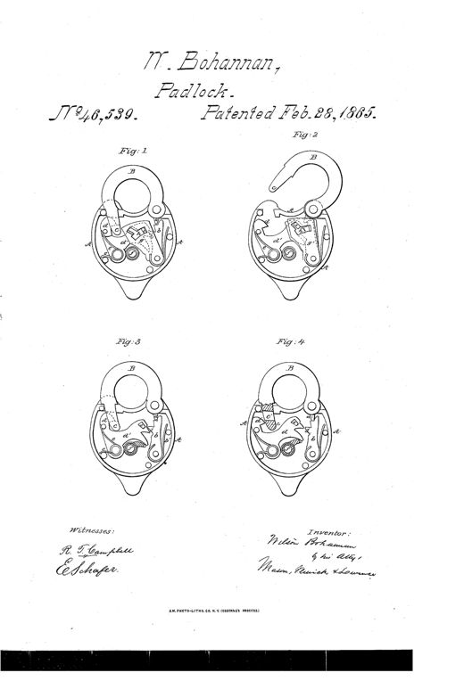
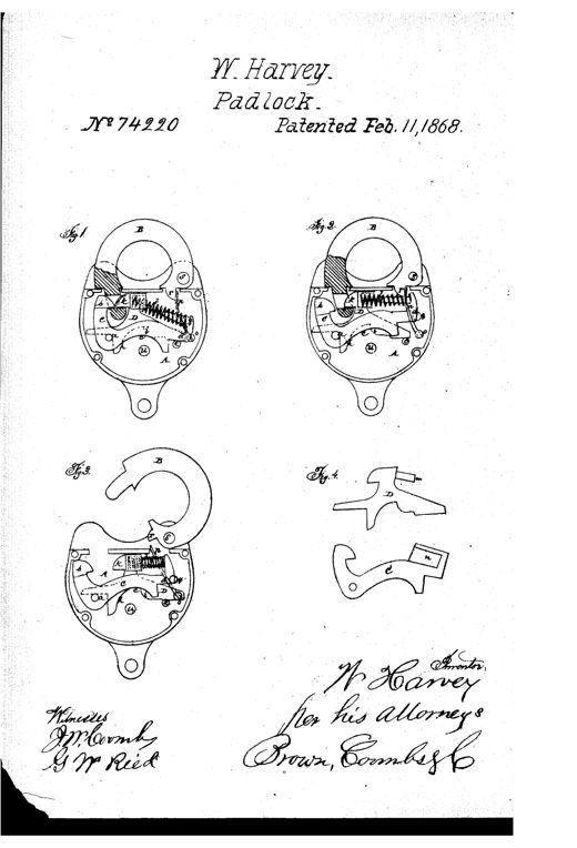
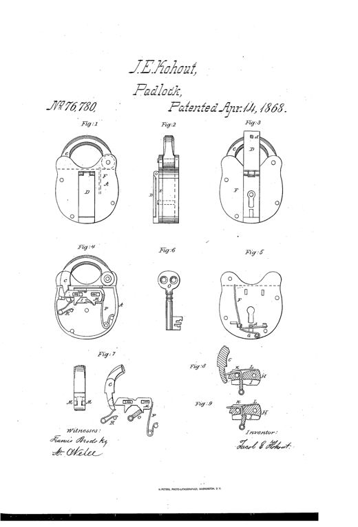
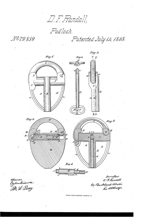
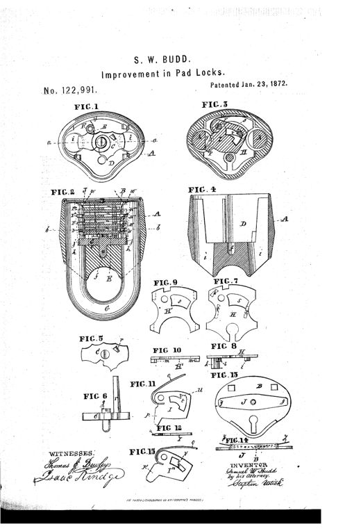
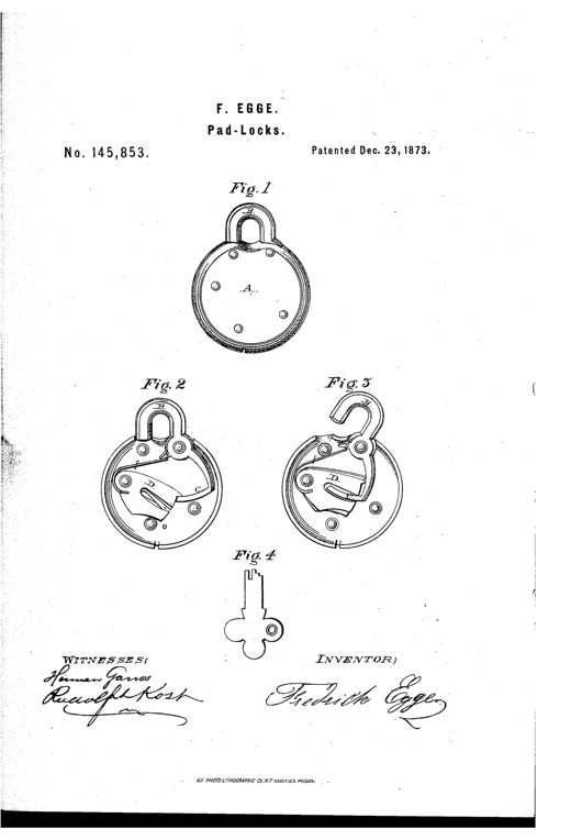
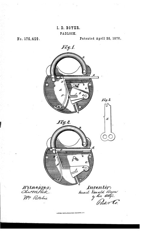
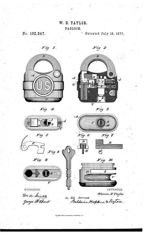
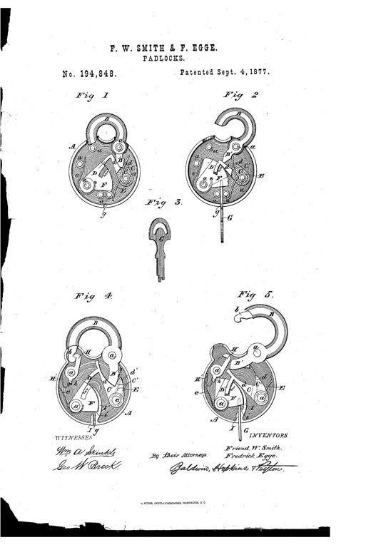
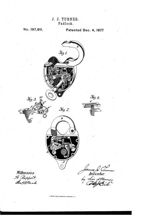
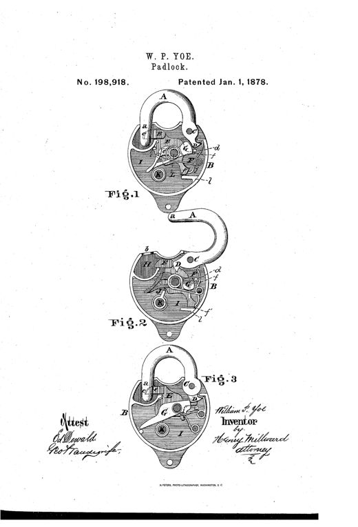
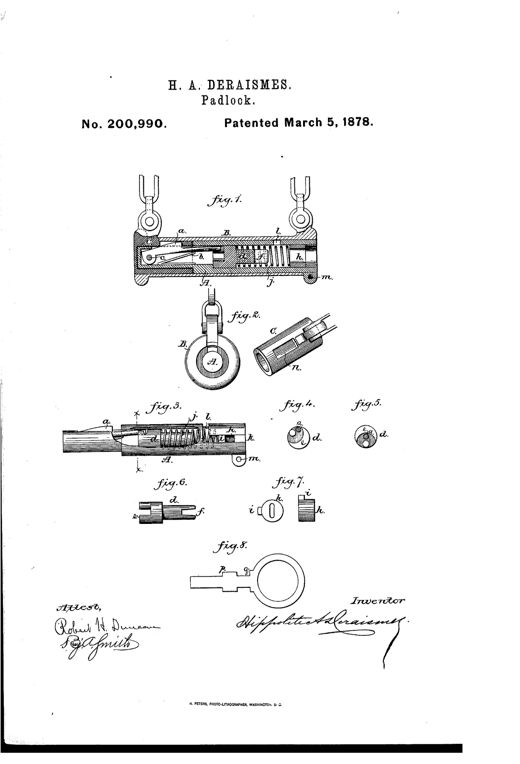
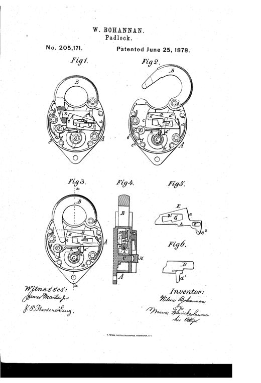
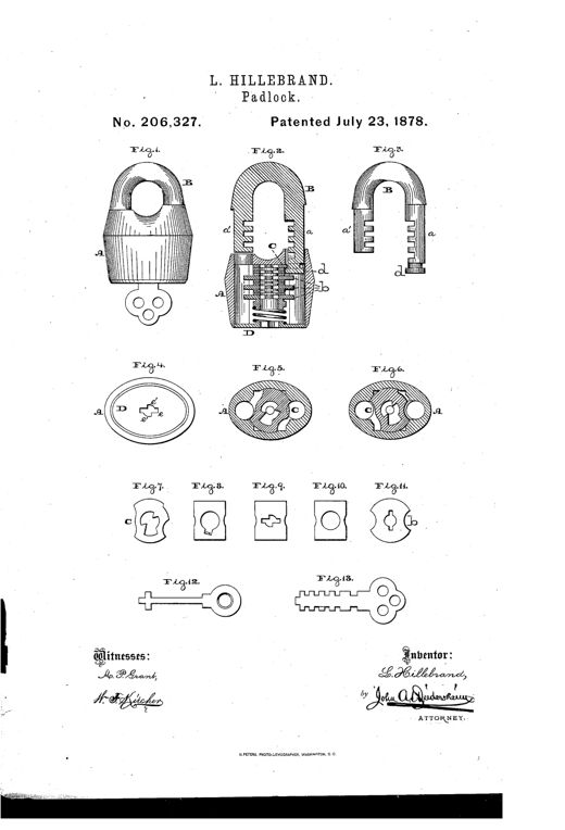
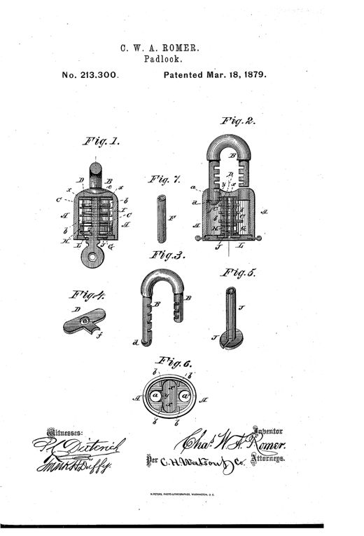
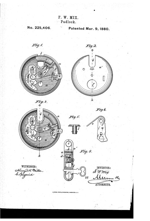
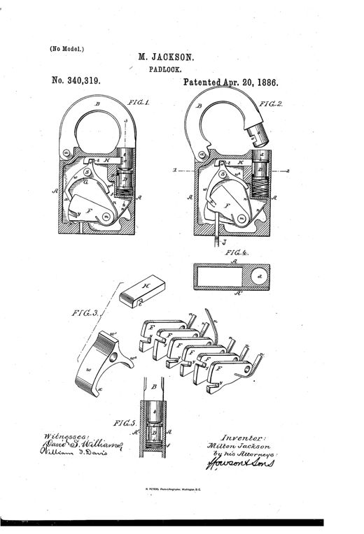
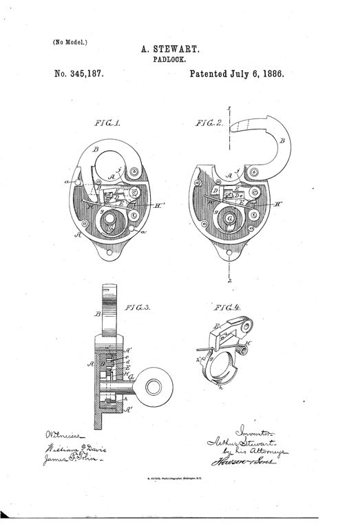
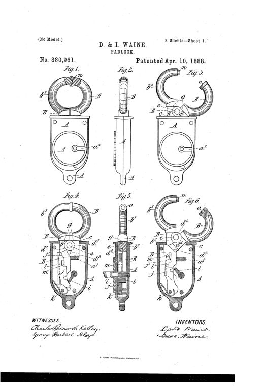
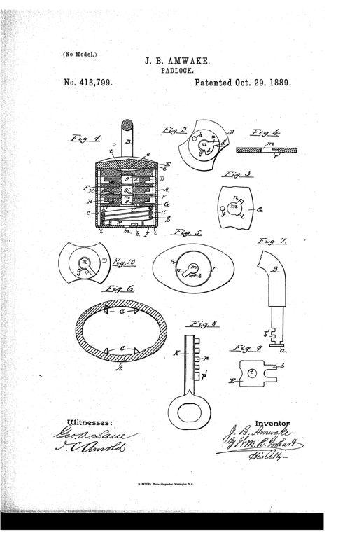
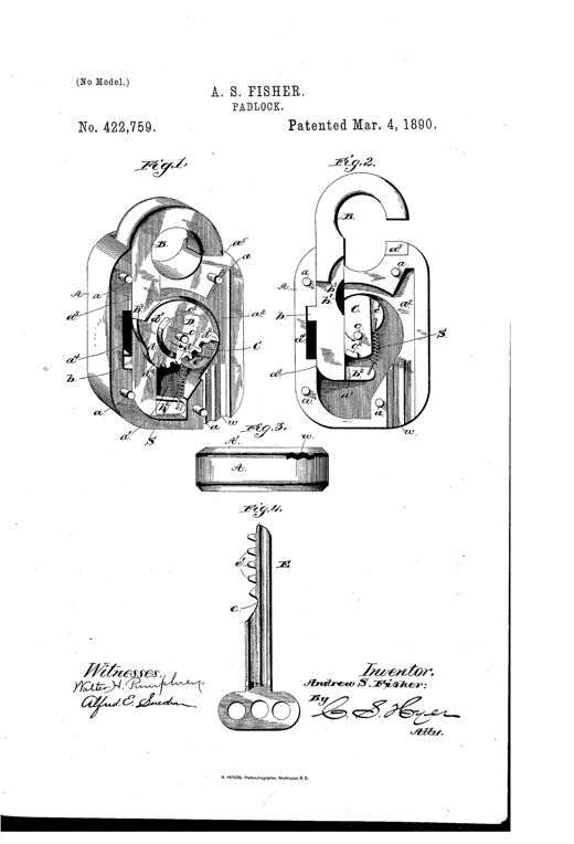
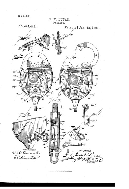
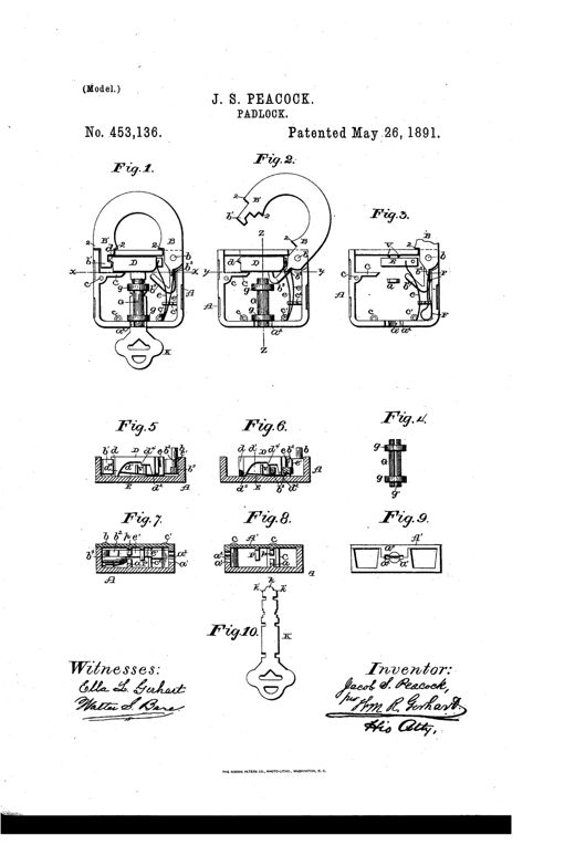
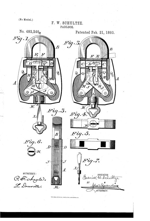
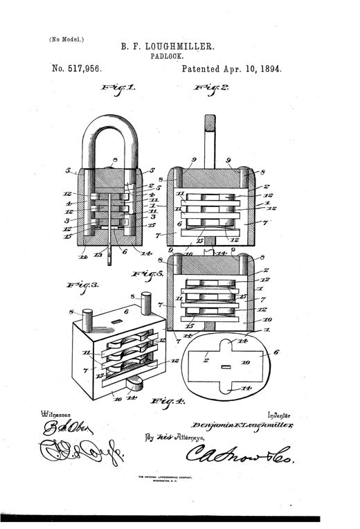
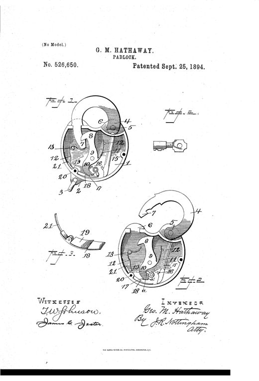
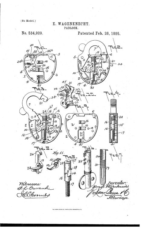
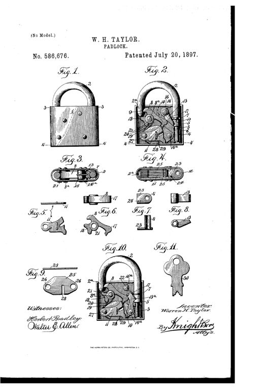
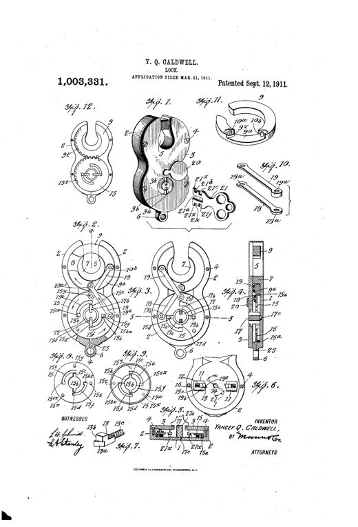
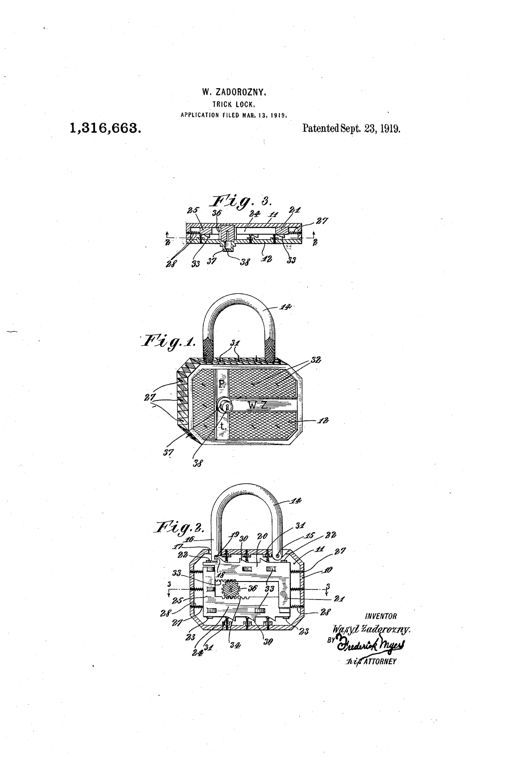
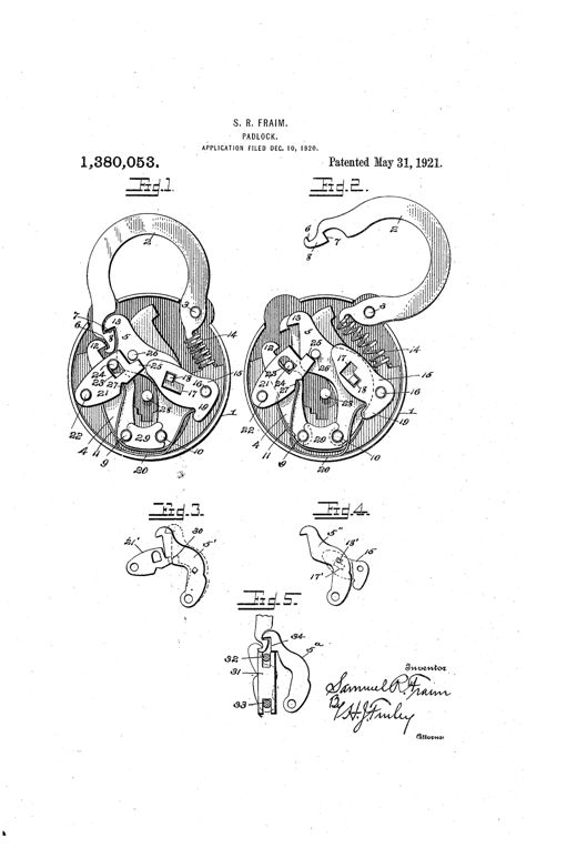
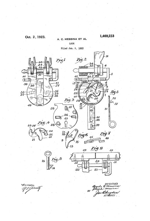
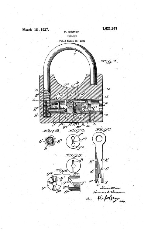
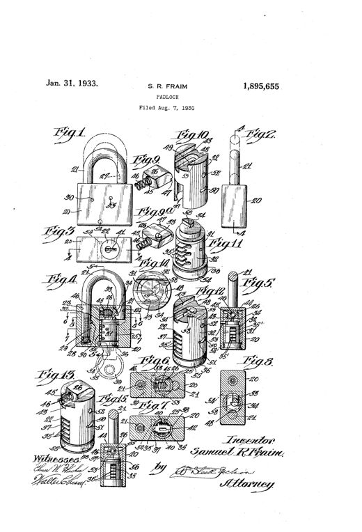
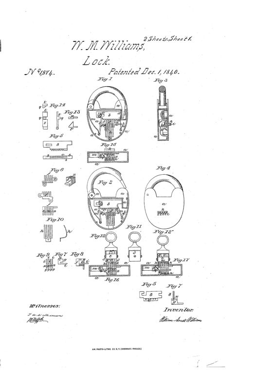
Patent drawing of a 19th-century padlock and door lock showing an internal toothed bolt rack, four spring-loaded sliding pieces in a rack box, a special multi-pin key, and adaptations to a rotary door lock and a liquor cask tap lock.LOCK AND KEYWilliam Morrett Williams · December 1, 1840Two front-view line drawings of a padlock, one showing the exterior with shackle labeled B, and one with the front plate removed revealing internal springs, levers, and a rotating disk mechanism, plus a small horizontal cross-section below.PADLOCKI. J. Oldis · January 1, 1856Patent drawing of a heart-shaped padlock shown in three cross-sectional views with shackle up and down, plus separate detail drawings of three tumblers, a bolt, a lever, and a barrel key.IMPROVEMENT IN PADLOCKSConrad Liebrich · August 11, 1863Patent drawing of a round padlock with a curved shackle, shown in exterior view, sectioned interior with divided stop-pins and a turning block, a separate flat key with two pins, and a rectangular door-lock variant with a similar pin mechanism.IMPROVEMENT IN LOCKS.Thomas George Harold · November 24, 1863Four line-drawing diagrams of a padlock's internal mechanism labeled Fig. 1 through Fig. 4, showing a curved shackle B pivoted into a rounded case A, with internal parts including a spring-pawl b, catch-plate d', hook d, tumblers g and g', and various numbered teeth and slots illustrating the locking and unlocking sequence.IMPROVEMENT IN PADLOCKSWilson Bohannan · February 28, 1865Patent drawing showing four views of a padlock's internal mechanism: three oval-shaped interior views (Figs. 1-3) revealing pivoted bolts, a coiled spring, and the shackle in various locked/unlocked positions, plus a fourth figure showing two separate curved bolt pieces labeled D and C with pivot holes and notches.IMPROVED PADLOCKWilliam Harvey · February 11, 1868Technical patent drawing of a heart-shaped padlock body with a curved shackle, hinged hasp, internal sliding bolts, springs, and a separate bit key, shown in nine labeled figures illustrating the lock's construction and operation.IMPROVEMENT IN PADLOCKSJacob E. Kohout · April 14, 1868Patent drawing sheet showing a heart-shaped padlock with a rounded shackle, internal cutaway views revealing the spring-loaded bolt and detent screw, and an elongated ridged key with a T-shaped handle.IMPROVEMENT IN PADLOCKSDavid F. Randall · July 14, 1868Patent drawing sheet showing fifteen numbered figures of a heart-shaped padlock case, including cross-sections revealing stacked lever tumblers, a pivoted bolt, a U-shaped shackle with slotted prongs, and detail views of individual tumbler and bridge-plate components.IMPROVEMENT IN PADLOCKSSamuel W. Budd · January 23, 1872Patent drawing of a round padlock showing its exterior with a curved shackle and hasp, plus two internal views revealing pivoted slotted tumblers and springs in locked and unlocked positions, alongside a flat key.IMPROVEMENT IN PADLOCKSFredrick Egge · December 23, 1873Two cutaway diagrams of a round padlock showing the internal bolt, tumblers, and spring mechanism with the shackle at top, alongside a drawing of the irregularly-shaped thrust key.IMPROVEMENT IN PADLOCKSIsrael Donald Boyer · April 25, 1876Patent drawing of a U.S.-marked padlock showing exterior view, internal cross-section with bolt and tumblers, and a double-bitted key.IMPROVEMENT IN PADLOCKSWarren H. Taylor · July 10, 1877Patent drawing of a round padlock showing internal dog, tumblers, and pivoted shackle mechanisms across five figures, with a separate key illustration.IMPROVEMENT IN PADLOCKSFriend W. Smith and Fredrick Egge · September 4, 1877Patent drawing of a heart-shaped padlock showing the internal mechanism with a pivoted tumbler, hooked arm, sliding bolt, springs, and a key inserted into the keyhole, alongside separate detail views of the tumbler/pawl assembly and the bolt.IMPROVEMENT IN PADLOCKSJames J. Turner · December 4, 1877Three sectional elevation drawings of a padlock showing internal mechanism including a pivoted shackle, spring-loaded lock-bolt, swinging dog, and key pin, labeled with letters A through L across Figures 1, 2, and 3.IMPROVEMENT IN PADLOCKSWilliam P. Yoe · January 1, 1878Patent drawing of a tubular padlock showing a cylindrical lock case with a U-shaped shackle, internal cross-section revealing the bolt, spring, cam spindle and tumbler, plus separate detail views of the sliding clasp, spindle, tumbler, and a flat key with notched stem.IMPROVEMENT IN PADLOCKSHippolite A. Deraismes · March 5, 1878Patent drawing of a heart-shaped padlock case with a pivoted curved shackle, internal spring-loaded bolt and tumbler mechanism, and separate detail views of the tumbler and bolt components.IMPROVEMENT IN PADLOCKSWilson Bohannan · June 25, 1878Patent drawing of a padlock showing its rounded U-shaped shackle, internal bolt mechanism in cross-section, lock cover with a cross-shaped keyhole, and two distinct flat keys used to operate the locking bolts and an independent shackle-retaining bolt.IMPROVEMENT IN PADLOCKSLouis Hillebrand · July 23, 1878Patent drawing of a padlock showing cross-sections of the shell with tumblers, the U-shaped shackle with a lug, a locking-plate, key-tube, and an inverted view of the case.IMPROVEMENT IN PADLOCKSCharles W. A. Romer · March 18, 1879Patent drawing of a padlock showing an internal rotating notched disk, gear segment, spring, anchor, and key mechanism in cross-section, with a shackle and a separate bent key illustrated below.IMPROVEMENT IN PADLOCKSConrad Jensen · September 30, 1879Technical patent drawing showing the circular internal mechanism of a padlock with a curved vibrating bolt, pivoted lever, spring-loaded blocking piece, and a separate key-post and tumbler piece, alongside a cross-section view showing a barrel key inserted into the lock.Padlock.Frank W. Mix · March 9, 1880Patent drawing of a padlock showing a curved metal shackle, internal notched tumblers, a pivoted dog, and a sliding bolt mechanism in cross-section, with separate detail views of the tumbler stack and key.PADLOCK.Milton Jackson · April 20, 1886Patent drawing of a padlock showing four figures: two face views of the lock body with shackle open and closed revealing internal bolt and tumbler mechanism, a cross-section with the key inserted, and a detached perspective of the tumbler piece.PADLOCK.Arthur Stewart · July 6, 1886Patent drawing sheets showing a padlock with a round hinged shackle, internal bolt and lever tumbler mechanism, and a key inserted into the case, with multiple cross-sectional and detail views labeled with reference letters.PADLOCKDavid Waine and Isaac Waine · April 10, 1888Patent drawing of a cylindrical padlock showing a cross-section with a U-shaped shackle, stacked internal tumbler plates labeled with letters, and several smaller diagrams of the individual tumblers, plates, and a bit key.PADLOCK.Jacob B. Amwake · October 29, 1889Patent drawing of a padlock showing the shackle, an internal eccentric dog and toothed tumbler mechanism, and a separate corrugated key with matching teeth.PADLOCK.Andrew S. Fisher · March 4, 1890Patent drawing of a railway switch padlock showing the internal mechanism with shackle, tumblers, spring-loaded bolt, lever, and bell alarm, along with detail views of the key, tumbler-locking device, and case components labeled with reference letters.PADLOCK.George William Lucas · January 13, 1891Patent drawing of a padlock showing a U-shaped shackle, internal transverse bolt, springs, revoluble key-guide, and a barrel key with notched wards.PADLOCKJacob S. Peacock · May 26, 1891Patent drawing of a padlock showing a U-shaped shackle inserted into a casing containing pivoted tumblers, sliding dogs, springs, and a twisted key mechanism, with seven labeled figures illustrating the internal parts and key.PADLOCK.Frederick W. Schultze · February 21, 1893Patent drawing of an 1894 padlock showing five figures: a cutaway shackle-and-casing assembly with numbered internal tumblers and springs, a perspective view of the internal locking frame with stacked notched tumblers, and a bottom plan view of the lock casing with keyhole and slot details.PADLOCK.Benjamin F. Loughmiller · April 10, 1894Patent drawing of a padlock with side plate removed showing internal shackle, spring-loaded tumblers, locking-dog, and key-locking bar, plus a separate key and locking-dog detail views.PADLOCKGeorge M. Hathaway · September 25, 1894Technical patent drawing showing exploded and sectional views of a padlock's internal casing, shackle, tumblers, dogs, catches, and a threaded key, with numbered reference lines identifying each part.PADLOCK.Ernst Wagenknecht · February 26, 1895Patent drawing of a padlock showing exterior view, internal bolt-and-tumbler mechanism with numbered parts, cross-sections, individual component details, and the setting key.PADLOCK.Warren H. Taylor · July 20, 1897Patent drawing sheet showing an exploded padlock with an arc-shaped shackle, circular actuator plate with teeth and slots, cam members, connecting links, and a multi-pronged key, alongside cross-sectional and detail views labeled with numbered reference lines.LOCKYancey Q. Caldwell · September 12, 1911Three patent drawings of a padlock: an exterior perspective view marked 'WZ' with a keyhole, a vertical cross-section showing internal sliding bars, springs, and pins, and a horizontal cross-section showing the pinion and rack-toothed bars inside the casing.TRICK-LOCKWasyl Zadorozny · September 23, 1919Patent drawing of a round padlock showing internal tumbler mechanism, pivoted shackle, springs, and numbered parts across five figures, with the inventor's signature at the bottom.PADLOCKSamuel R. Fraim · May 31, 1921Patent drawing sheet showing nine figures of a circular padlock mechanism: an assembled front view with looped hasp links, an exploded interior view revealing stacked tumblers and a pivoting locking bolt, a separate cover plate with slots, a perspective locking bolt with curved ends, a hasp element, a tumbler and spring, a latching device, a bitted key, and a modified door-mounting hasp assembly with screws.LOCKAngelo C. Messina and Joseph Messina · October 2, 1923Cutaway drawing of a padlock showing a rounded shackle, internal rotating lock cylinder with spring-loaded bolt, and a flat notched key beside smaller detail views of the crown, sleeves, and bore cross-sections.PADLOCKHeinrich Biemer · March 15, 1927Patent drawing sheet showing a padlock with a U-shaped shackle and rectangular body, alongside detailed exploded and sectional views of the internal disc-tumbler lock insert, casing, bolt, and key plug components labeled with numbered reference lines.PADLOCKSamuel R. Fraim · January 31, 1933