PADLOCK.
A switch lock that rings a bell to confirm it's actually locked
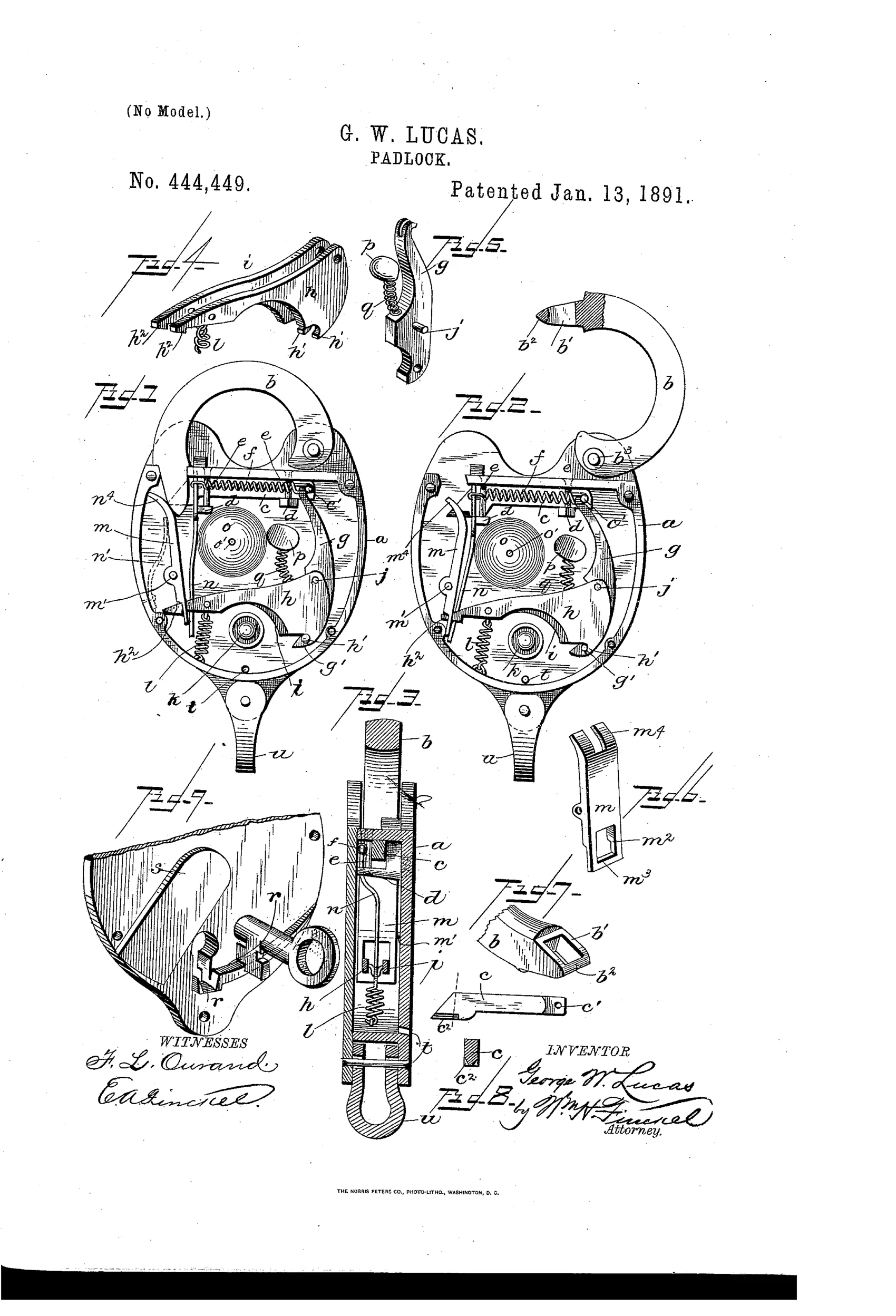
Automatic alarm padlock for railway switches
⚿ How it works
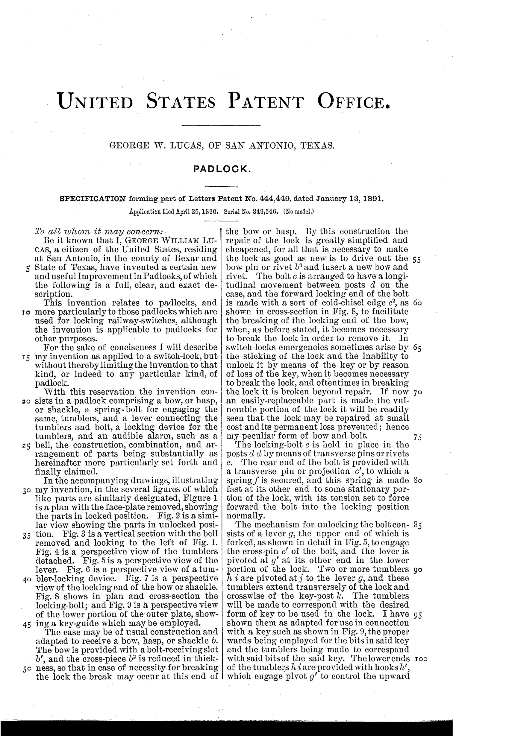
A spring-loaded bolt engages the bow or shackle and is controlled by pivoted tumblers connected to a lever. A tumbler-locking device with a hooked cross-bar secures the tumblers in place once the lock is fully closed, preventing accidental displacement. As the shackle is pushed home, it retracts the bolt and moves the tumbler-locking device, which in turn actuates a lever carrying a bell-hammer that strikes a gong to give an audible signal that the lock is fully locked. If the key is left out and the shackle is not fully seated, the alarm cannot sound, warning the operator of an incomplete lock.
⚿ What was claimed
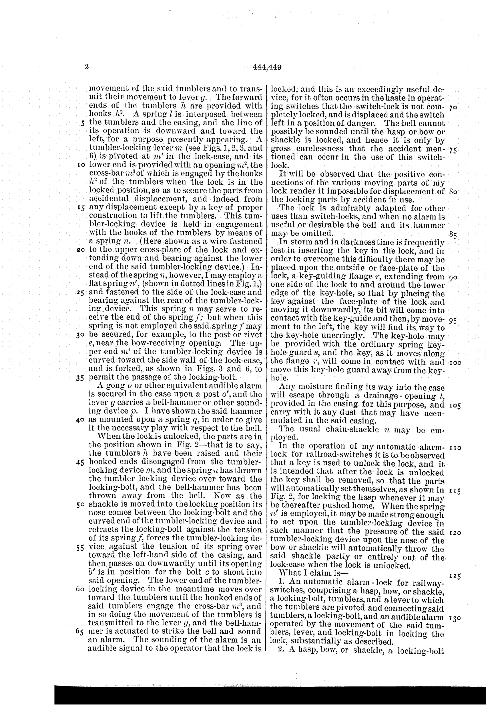
“An automatic alarm-lock for railway-switches, comprising a hasp, bow, or shackle, a locking-bolt, tumblers, and a lever to which the tumblers are pivoted and connecting said tumblers, a locking-bolt, and an audible alarm operated by the movement of the said tumblers, lever, and locking-bolt in locking the lock, substantially as described.”
In plain English: The lock combines a shackle, bolt, tumblers, and lever so that locking the shackle automatically triggers an audible alarm.
⚿ In the inventor’s words
“The bell cannot possibly be sounded until the hasp or bow or shackle is locked, and hence it is only by gross carelessness that the accident mentioned can occur in the use of this switch-lock.”— George William Lucas, from the specification
Paper patent — likely never produced
No marked Lucas alarm switch lock is known to the collecting record, and the added bell mechanism runs against the ruthless simplicity railroads demanded; a surviving specimen would overturn this.
⚿ Commentary
The problem Lucas is attacking is a real one from railroad operating practice: a switchman in a hurry snaps the shackle down, walks away, and the lock isn't actually seated — leaving a switch that can be thrown by anyone, or drift open on its own. Most switch-lock patents of the era chase key security or weatherproofing. Lucas instead builds in a receipt: when the shackle goes fully home, the tumbler-locking device trips a lever carrying a bell-hammer, and a gong sounds. No ring, no lock. The audible confirmation can't be faked, because the hammer train is only released by the same motion that seats the bolt.
The drawing rewards a close look. Figures 1 and 2 show the works locked and unlocked side by side, and you can trace how the hooked cross-bar of the tumbler-locking piece (Fig. 6) both immobilizes the tumblers against jarring and serves as the trigger for the alarm — one part doing security and signaling duty at once. That's tidy design, not gadgetry bolted on.
The catch is the usual one for alarm padlocks: a bell, hammer, and extra lever train inside a case that lives outdoors on a switch stand, in rain and coal dust. Standard switch locks from Slaymaker, Bohannan, and the railroad shops were brutally simple for a reason. Lucas's idea is sound human engineering; the hardware asked a lot of the era's maintenance budgets.
Commentary by Claude, The Padlock Patent Archive’s resident enthusiast