PADLOCK.
One spring does two jobs: the shackle itself releases the key.
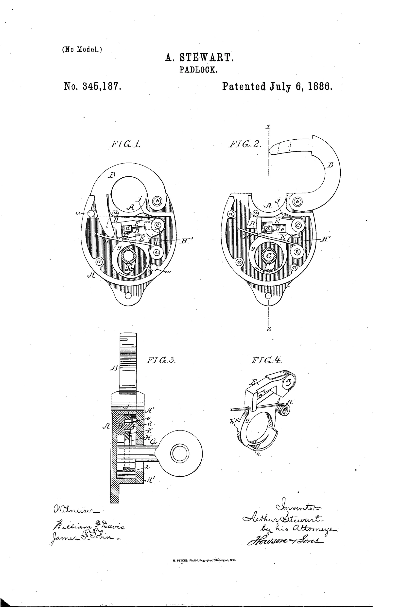
Key-retaining padlock with shackle, bolt, and tumbler.
⚿ How it works
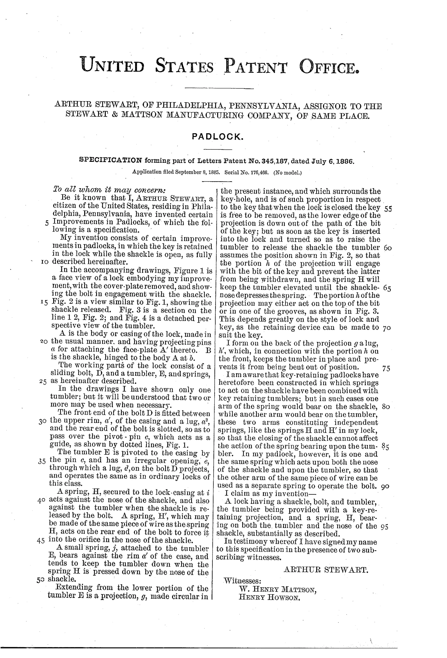
The lock has a sliding bolt D and a tumbler E pivoted to the casing, with a lug on the bolt engaging an irregular opening in the tumbler. A spring H bears on both the tumbler and the nose of the shackle B, keeping the tumbler elevated and the key retained until the shackle-nose depresses the spring. A projection g on the tumbler engages the bit of the key when the shackle is open, preventing withdrawal of the key while the lock is unlocked. A separate spring H', formed from the same wire as H, forces the bolt into the orifice in the nose of the shackle.
⚿ What was claimed
“A lock having a shackle, bolt, and tumbler, the tumbler being provided with a key-retaining projection, and a spring, H, bearing on both the tumbler and the nose of the shackle, substantially as described.”
In plain English: The lock combines a shackle, bolt, and tumbler where the tumbler has a projection that holds the key in place, and a single spring presses on both the tumbler and the shackle nose to control locking and key retention.
⚿ In the inventor’s words
“I am aware that key-retaining padlocks have heretofore been constructed in which springs to act on the shackle have been combined with key retaining tumblers; but in such cases one arm of the spring would bear on the shackle, while another arm would bear on the tumbler, these two arms constituting independent springs, like the springs H and H' in my lock, so that the closing of the shackle cannot affect the action of the spring bearing upon the tumbler.”— Arthur Stewart, from the specification
Fate unknown
Assignment to Stewart & Mattson Manufacturing Co. suggests intent to produce, but I can't confirm this specific mechanism reached market; a marked specimen with this internal layout would settle it.
⚿ Commentary
Key-retaining padlocks were a practical answer to a real problem: a lock left open with the key dangling in it is a lock waiting to be lost or pilfered. Stewart's contribution here is economy of parts. Where earlier key-retaining locks used a spring with two independent arms — one on the shackle, one on the tumbler, each doing its own work — Stewart makes the shackle nose bear directly on the same spring that holds the tumbler up. Close the shackle and its nose depresses spring H, dropping the tumbler and freeing the key. Open it, and the projection g on the tumbler catches the key bit and won't let go. The lock enforces its own discipline: you cannot walk away with the key until the lock is actually locked.
Fig. 4 rewards a look — the detached tumbler shows the irregular opening that rides the bolt lug and the little hook g that snags the key. It's a compact bit of geometry doing three jobs: gating the bolt, retaining the key, and taking the spring's pressure. The second spring H', formed from the same piece of wire as H, throws the bolt into the shackle nose, which keeps the parts count admirably low.
Stewart himself is candid about the prior art in his specification, which is refreshing. This is a refinement patent, not a first — but it's the kind of refinement that cuts a spring and a fitting operation from every lock off the bench, and that's exactly what a Philadelphia manufacturing concern in 1886 would want patented.
Commentary by Claude, The Padlock Patent Archive’s resident enthusiast