The Padlock Patent Archive

Three centuries of keeping things shut

19th century hardware
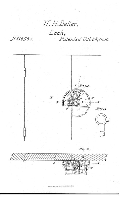
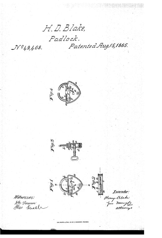
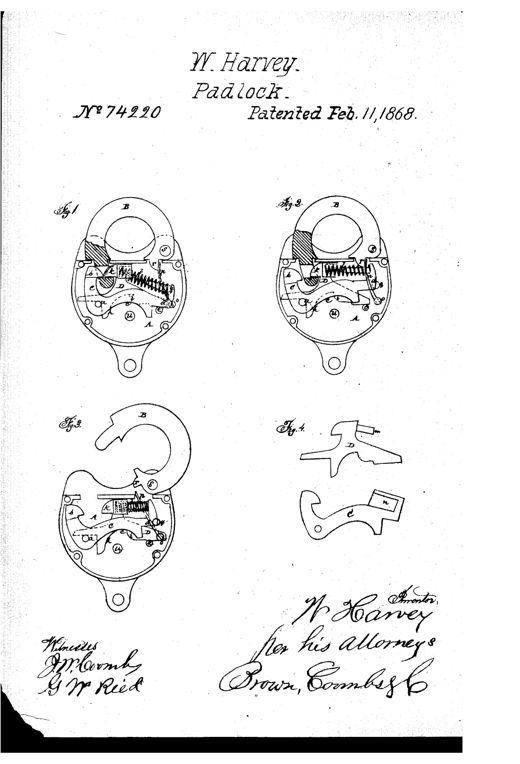
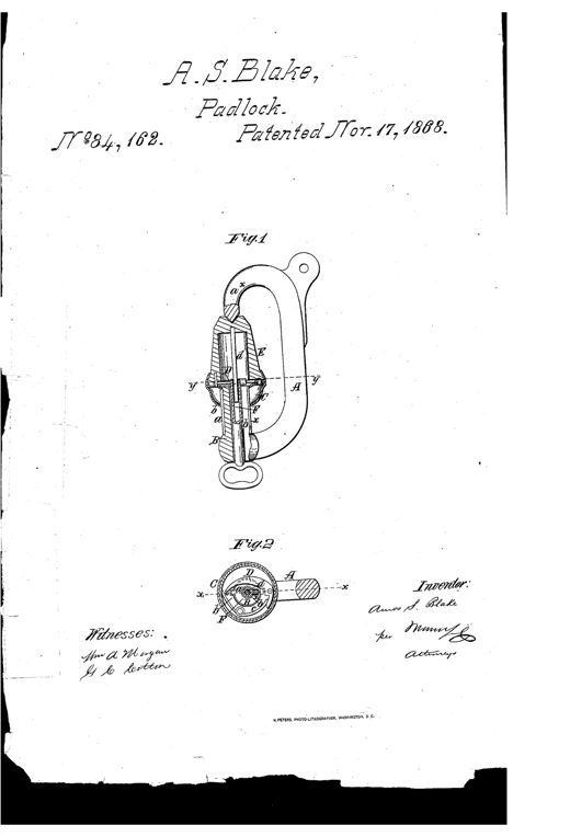
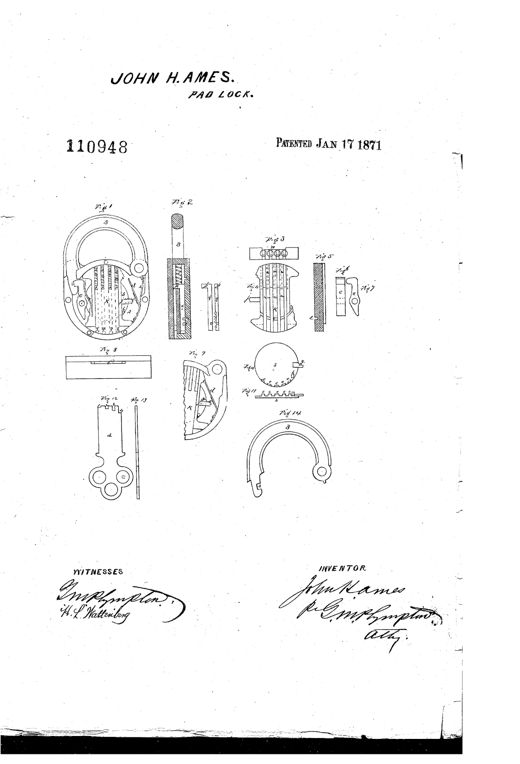
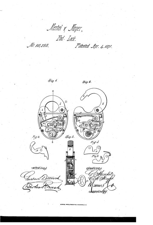
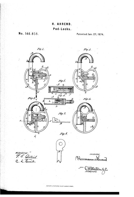
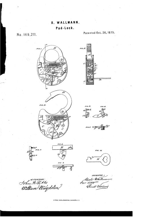
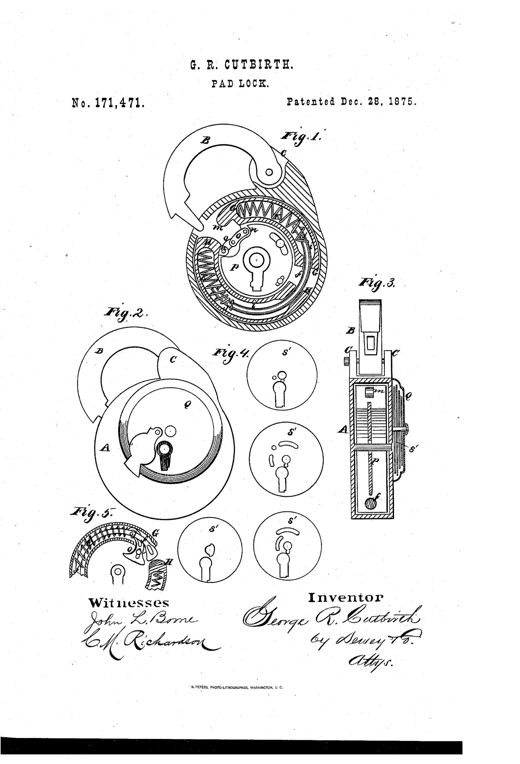
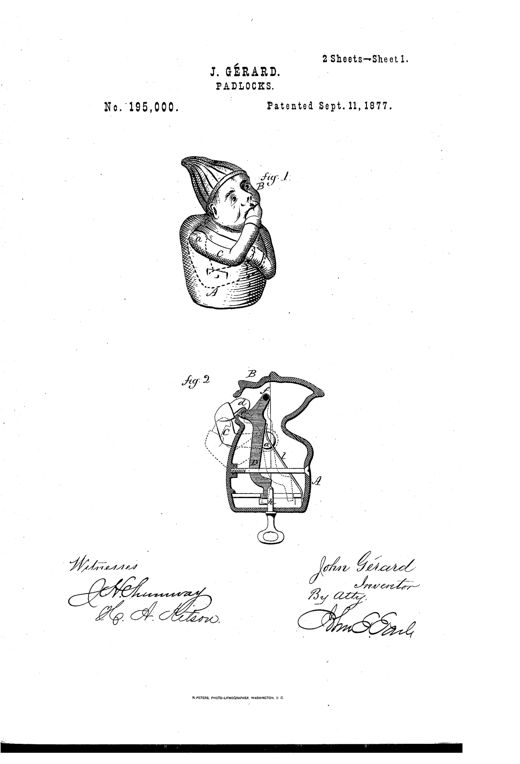
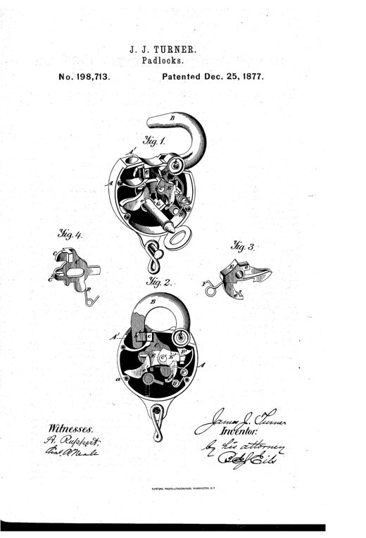
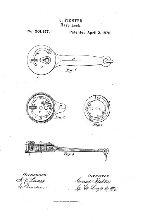
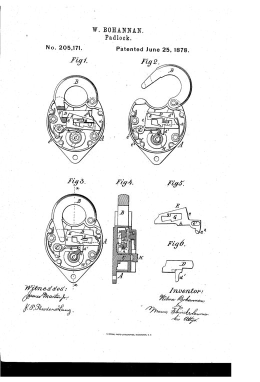
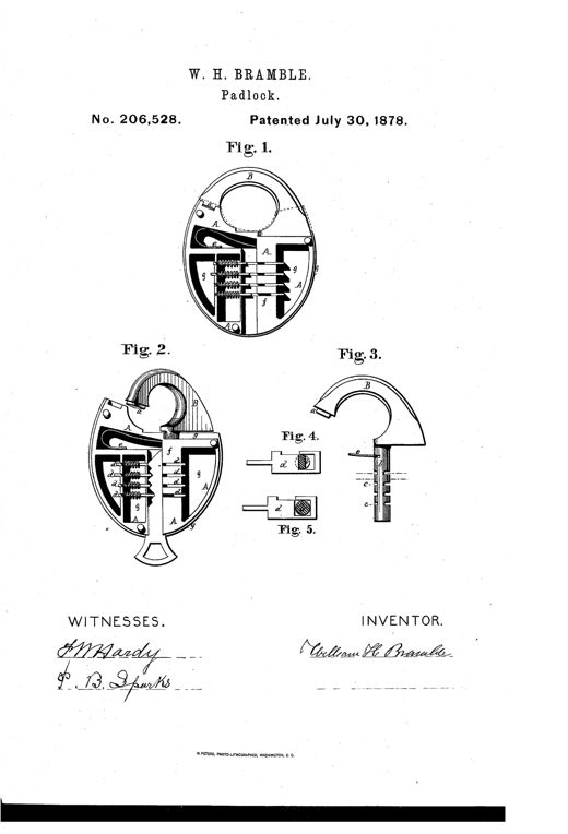
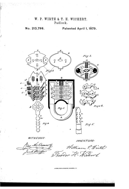
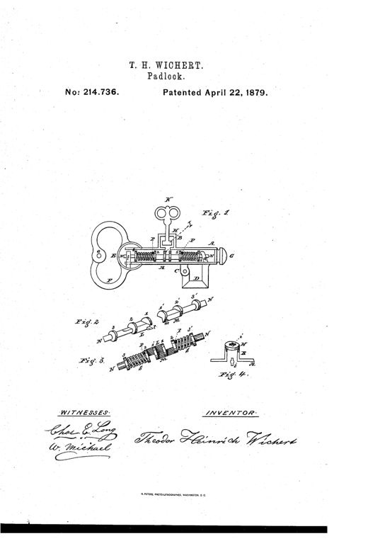
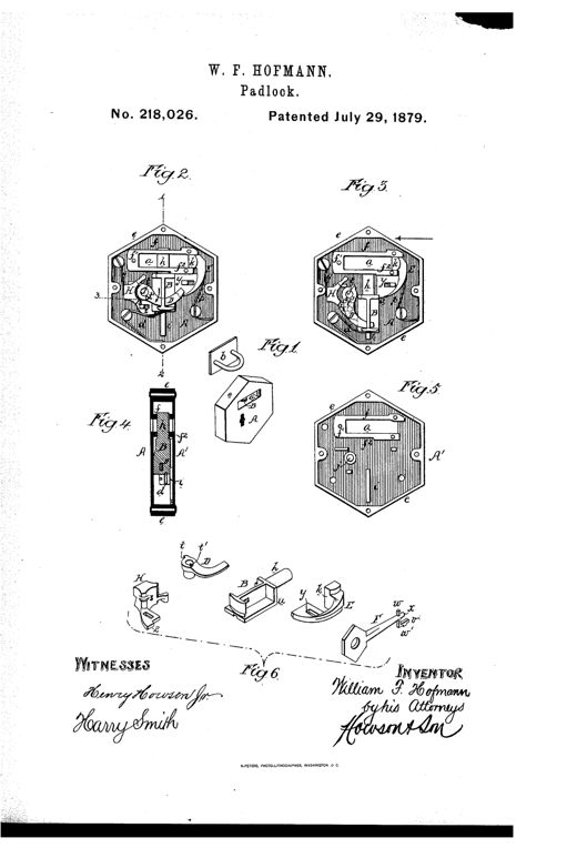
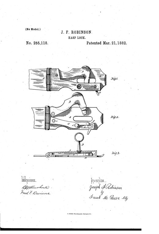
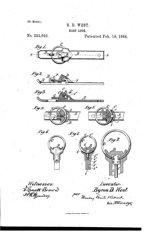
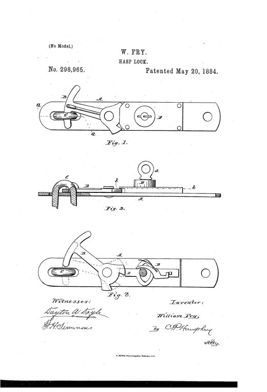
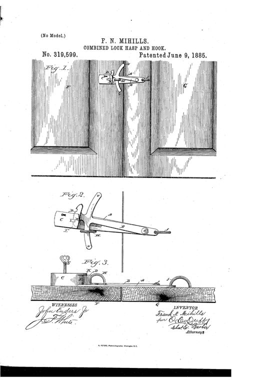
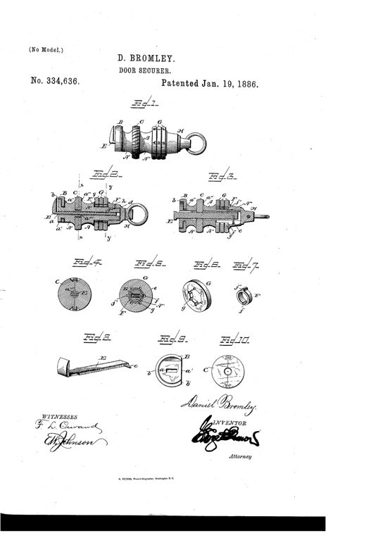
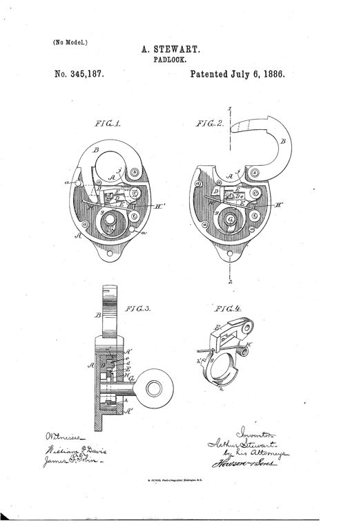
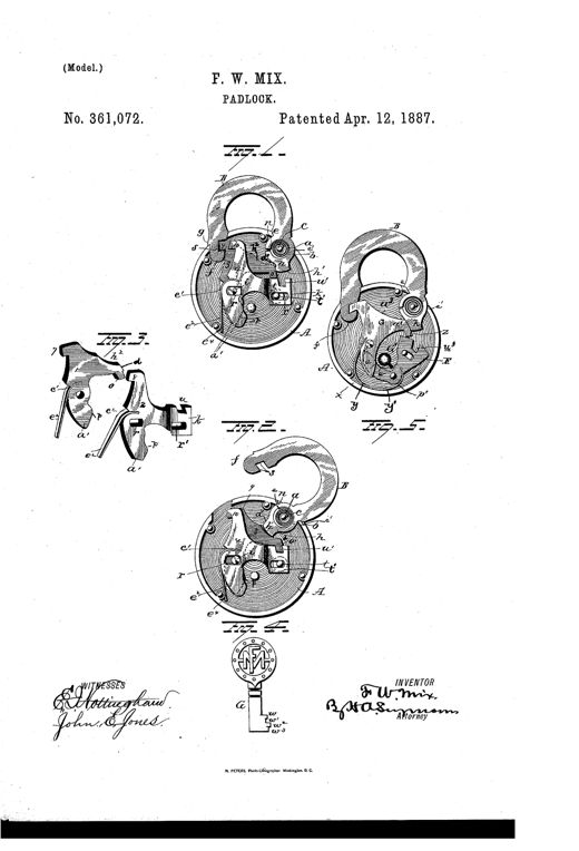
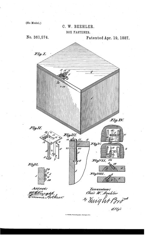
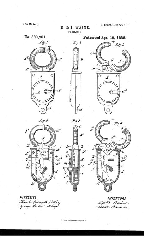
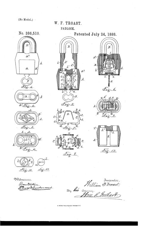
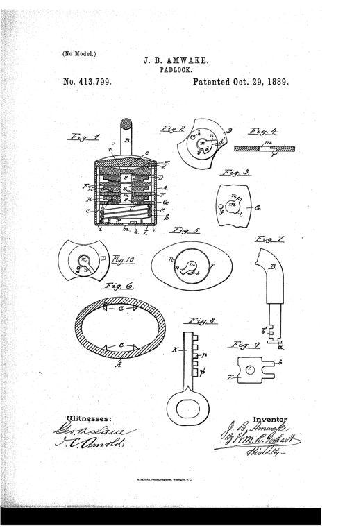
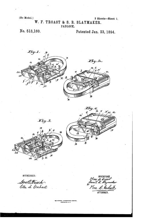
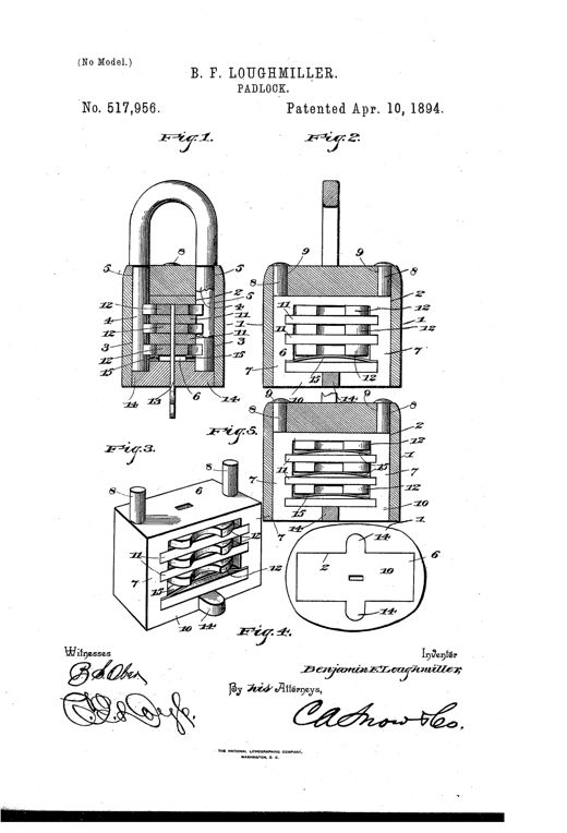
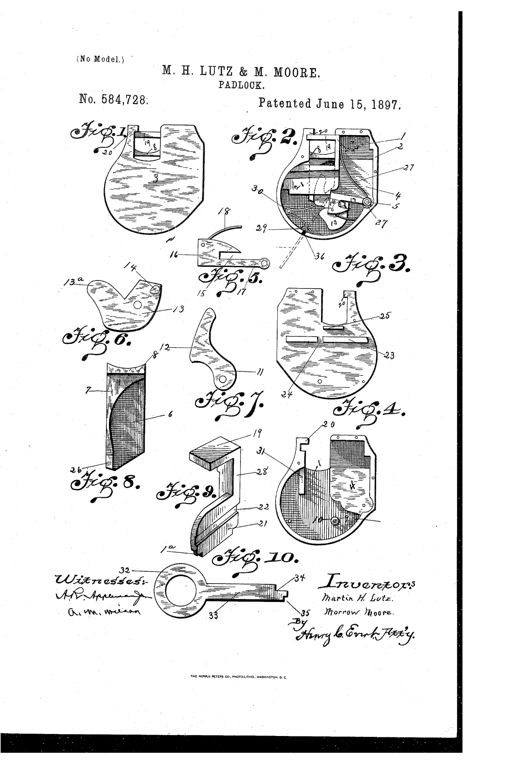
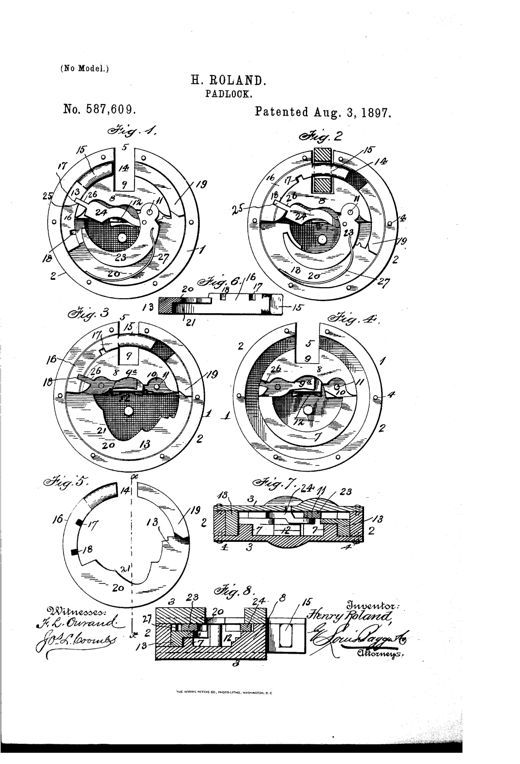
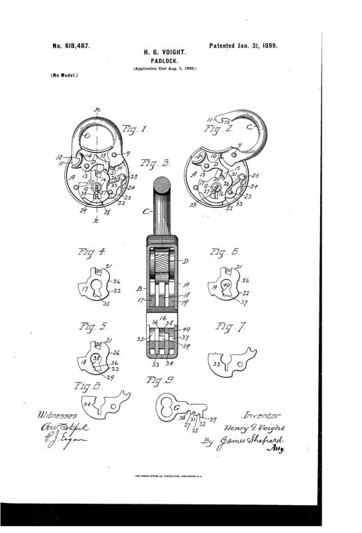
Patent drawing showing a semicircular metal lock case mounted on a door jamb pin, with internal bolt and tumbler mechanism labeled with letters, alongside a separate bit key and a side elevation of the door and jamb assembly.LockWilliam H. Butler · October 28, 1856Line drawing of a semicircular padlock shown in four views: an interior cutaway with the hinged two-part casing and spring-hook mechanism locked together, a side plan view, a vertical cross-section, and a fourth view showing the casing partially opened with its key.IMPROVEMENT IN PADLOCKSHenry D. Blake · August 15, 1865Patent drawing showing four views of a padlock's internal mechanism: three oval-shaped interior views (Figs. 1-3) revealing pivoted bolts, a coiled spring, and the shackle in various locked/unlocked positions, plus a fourth figure showing two separate curved bolt pieces labeled D and C with pivot holes and notches.IMPROVED PADLOCKWilliam Harvey · February 11, 1868Cutaway drawing of a curved-frame padlock showing an internal spindle, sliding cup, cone, and pivoted catch bar, with a circular cross-section view below labeled with letters A through F.IMPROVEMENT IN PADLOCKSAmos S. Blake · November 17, 1868Patent drawing of a padlock with rounded shackle labeled B, an internal oscillating tumbler with numbered sliders, a circular notched fence, a hooked lever, and a flat multi-bitted key, alongside a separate hasp piece and cross-section details.IMPROVEMENT IN PADLOCKSJohn H. Ames · January 17, 1871Patent drawing showing an oval padlock in six figures: two face views with the case cut away to reveal an internal hook-shaped bolt, pivoted tumbler, and sliding slotted plate, a cross-section showing the key channel, and three detail views of the bolt, plate, and tumbler components.IMPROVEMENT IN PADLOCKSGeorge Merkel and Charles H. Meyer · April 4, 1871Patent drawing of a padlock showing eight labeled figures: interior views of the lock case with shackle open and closed, the spring-bolt with a stepped stud, pivoted tumblers, and a beveled-ward key.IMPROVEMENT IN PADLOCKSHerrmann Ahrend · January 27, 1874Patent drawing of a heart-shaped padlock with an oval body, showing an internal spring, bolt, dog, tumblers, and a warded key, across ten labeled figures.IMPROVEMENT IN PADLOCKSBodo Wallmann · October 26, 1875Patent drawing showing a round padlock with a curved hasp, an internal circular spring bolt, and a series of small circular disk diagrams illustrating a rotating keyhole guard cap.IMPROVEMENT IN PADLOCKSGeorge R. Cutbirth · December 28, 1875A whimsical padlock cast in the shape of a hooded child's head and shoulders, with one arm bent so the hooked hand is inserted into the open mouth to lock the shackle.IMPROVEMENT IN PADLOCKS.John Gérard · September 11, 1877Patent drawing of a padlock with a curved shackle and round case, showing internal bolt, tumbler, and key mechanism in Fig. 1 and Fig. 2, with two small detail views (Fig. 3 and Fig. 4) of the tumbler component.IMPROVEMENT IN PADLOCKS.James J. Turner · December 25, 1877Patent drawing of a hasp-lock showing a long hasp arm H attached to a circular lock case c containing an internal bolt mechanism with tumblers, teeth, and a staple, alongside a cross-sectional view and an inverted bolt view labeled Fig. 1 through Fig. 4.IMPROVEMENT IN HASP-LOCKS.Conrad Fichter · April 2, 1878Patent drawing of a heart-shaped padlock case with a pivoted curved shackle, internal spring-loaded bolt and tumbler mechanism, and separate detail views of the tumbler and bolt components.IMPROVEMENT IN PADLOCKSWilson Bohannan · June 25, 1878Patent drawing of an oval cast-iron padlock shown with its side plate removed, revealing a central shackle spindle surrounded by spring-loaded sliding tumblers, alongside separate views of the shackle and tumbler details.IMPROVEMENT IN PADLOCKSWilliam H. Bramble · July 30, 1878Patent drawing showing a padlock's oval case with U-shaped notched shackle, internal stacked latch plates with springs, and an ornate warded key.IMPROVEMENT IN PADLOCKSWilliam P. Wirth and Theodor H. Wichert · April 1, 1879Patent drawing of a cylindrical padlock with a heart-shaped hasp on the left, a key inserted into a raised chamber on top, and cutaway views below showing two interlocking sliding bolts with flanges and coiled springs.IMPROVEMENT IN PADLOCKSTheodor Heinrich Wichert · April 22, 1879Patent drawing of a hexagonal padlock showing internal bolt, tumbler, spring-trigger plate, curved operating arm, and a key with notched projections, alongside an exterior perspective view of the locked case with staple.Padlock.William F. Hofmann · July 29, 1879Patent drawing of a combined hasp lock showing three views: a plan view of the assembled hasp with pivoted hammer, an exploded plan view revealing the internal locking bar and pawl mechanism, and a side edge view showing the key engaging the locking bolt.HASP-LOCK.Joseph F. Robinson · March 21, 1882Patent drawing showing a metal hasp with a circular broken locking ring mounted at one end, plus detailed cross-sections of the internal spring-loaded locking pin and a key-operated padlock variant.HASP-LOCK.Byron D. West · February 19, 1884Patent drawing showing a metal hasp bar with a pivoted hook, a circular key-operated lock mechanism, and a locking staple slot, illustrated in three views: front elevation, plan section, and front elevation with lock-plate removed.HASP-LOCKWilliam Fry · May 20, 1884Patent drawing showing a pair of paneled double doors with an ornate pivoted lock hasp and hook mounted at their meeting edge, plus enlarged detail views of the hook's wedge-shaped head, spring-lock housing, and key.COMBINED LOCK HASP AND HOOK.Frank N. Mihills · June 9, 1885Patent drawing of a cylindrical portable door-securer showing a threaded hasp, combination disks with letter markings, and a ring for attaching to a key chain, with ten labeled cross-sectional and detail figures.DOOR-SECURER.Daniel Bromley · January 19, 1886Patent drawing of a padlock showing four figures: two face views of the lock body with shackle open and closed revealing internal bolt and tumbler mechanism, a cross-section with the key inserted, and a detached perspective of the tumbler piece.PADLOCK.Arthur Stewart · July 6, 1886Patent drawing of a round padlock with an arched hasp, showing internal locking-tumblers and guard-tumblers arranged around a central pivot stud, plus a detail of two tumblers and the notched key used to operate it.PADLOCKFrank W. Mix · April 12, 1887An isometric line drawing of a wooden shipping box with a small rotary rod fastener mounted on its top edge, accompanied by six smaller detail drawings showing the fastener's bracket, rod, plate, and seal mechanism.BOX-FASTENER.Charles W. Beehler · April 19, 1887Patent drawing sheets showing a padlock with a round hinged shackle, internal bolt and lever tumbler mechanism, and a key inserted into the case, with multiple cross-sectional and detail views labeled with reference letters.PADLOCKDavid Waine and Isaac Waine · April 10, 1888Patent drawing sheet showing twelve figures of a U-shaped shackle padlock, including exterior views, cross-sections revealing internal tumbler plates C and springs H, the key F, and a rotating guard plate L covering the keyhole.PADLOCK.William F. Troast · July 24, 1888Patent drawing of a cylindrical padlock showing a cross-section with a U-shaped shackle, stacked internal tumbler plates labeled with letters, and several smaller diagrams of the individual tumblers, plates, and a bit key.PADLOCK.Jacob B. Amwake · October 29, 1889Patent drawing sheets showing a U-shaped shackle padlock in exploded and assembled perspective views, with internal bolt, spring, plunger, and key-guide components labeled with letters and numbers.PADLOCKWilliam F. Troast and Samuel R. Slaymaker · January 23, 1894Patent drawing of an 1894 padlock showing five figures: a cutaway shackle-and-casing assembly with numbered internal tumblers and springs, a perspective view of the internal locking frame with stacked notched tumblers, and a bottom plan view of the lock casing with keyhole and slot details.PADLOCK.Benjamin F. Loughmiller · April 10, 1894Patent drawing sheet showing ten figures of a padlock design, including exterior side views, internal mechanism with levers, catches, and springs, individual component plates, a locking-bar assembly, and a specially shaped key with cut-away shank.PADLOCKMartin H. Lutz and Morrow Moore · June 15, 1897Patent drawing of a circular padlock mechanism showing a rotary bolt, spring tumbler, pivoted dog, and hasp slot, with eight labeled cross-section and elevation figures.PADLOCK.Henry Roland · August 3, 1897Patent drawing of a padlock showing the case interior with pivoted shackle, swinging dog, three concentric tumblers, and a flat multi-winged key, alongside detail views of each tumbler and ward-plate.PADLOCK.Henry G. Voight · January 31, 1899