PADLOCK.
A bolt that travels in a circle: Roland's ring-shaped shackle-catcher from Hazleton
Key-operated padlock with rotary segmental bolt
⚿ How it works
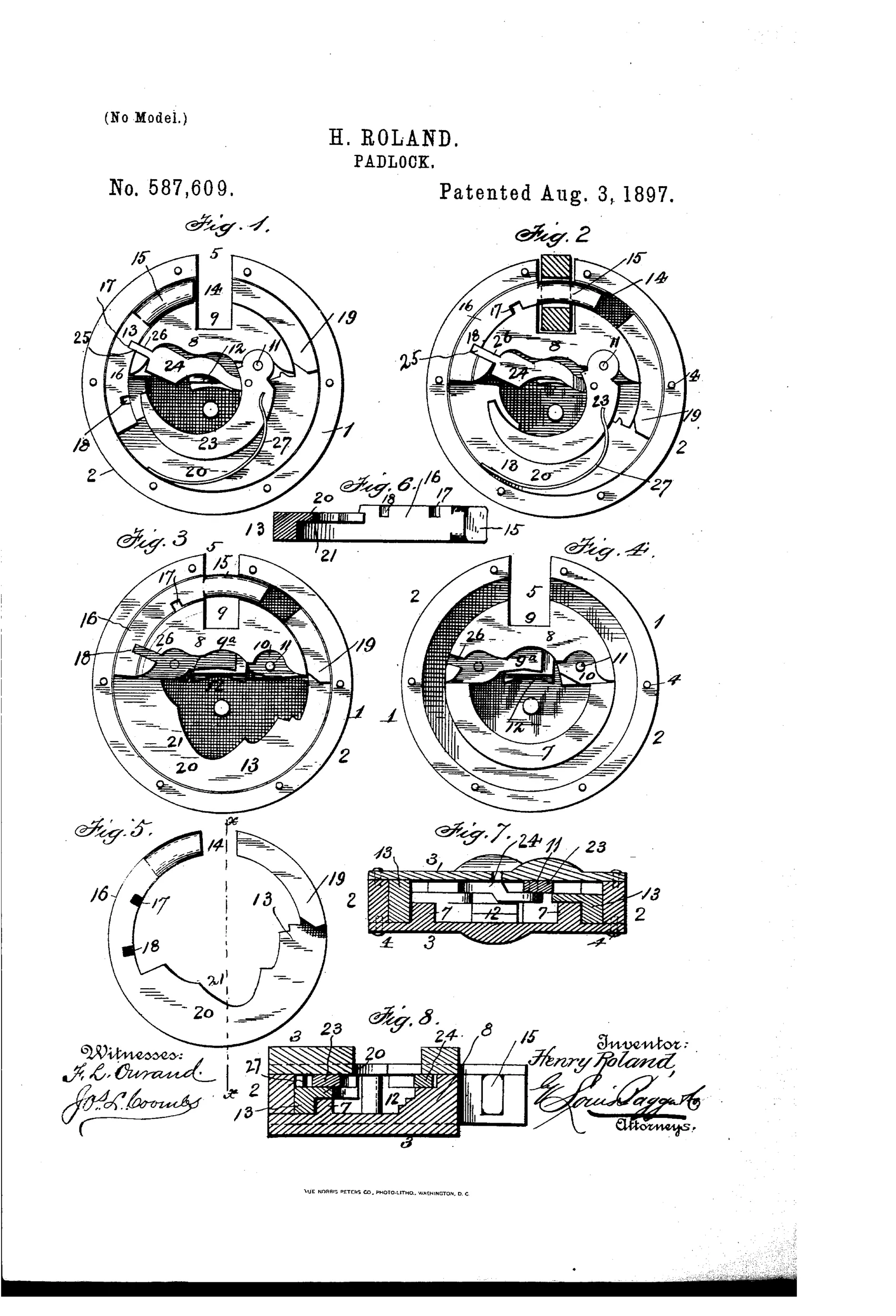
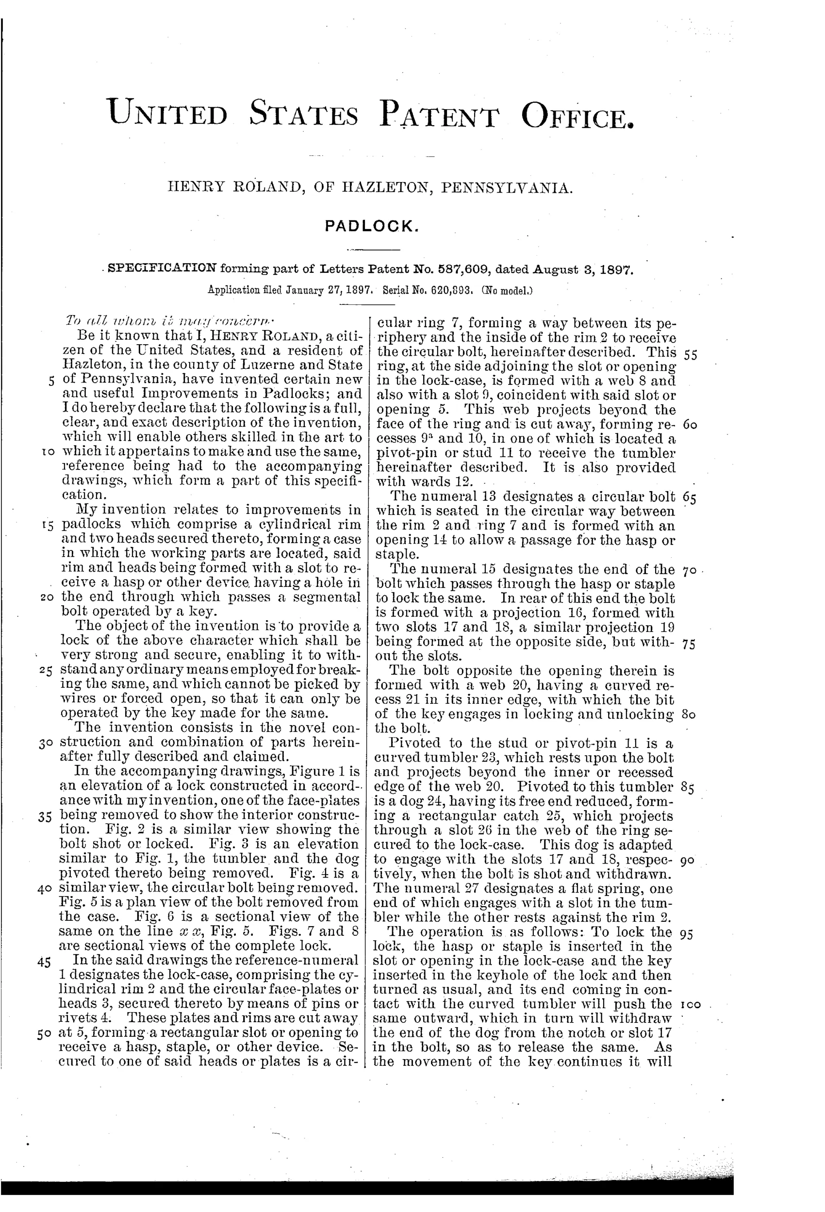
The lock case comprises a cylindrical rim and two heads forming a slot for a hasp or staple, with a circular ring secured concentric to the rim. A circular bolt seated between the ring and rim has an opening for the hasp and a web with a curved recess engaged by the key bit. A spring-actuated tumbler pivoted on a stud carries a dog whose free end engages slots in the bolt's projection to lock or release it as the key turns, so the bolt shoots across the case opening and through the hasp to lock, and withdraws to unlock only with the correct key.
⚿ What was claimed
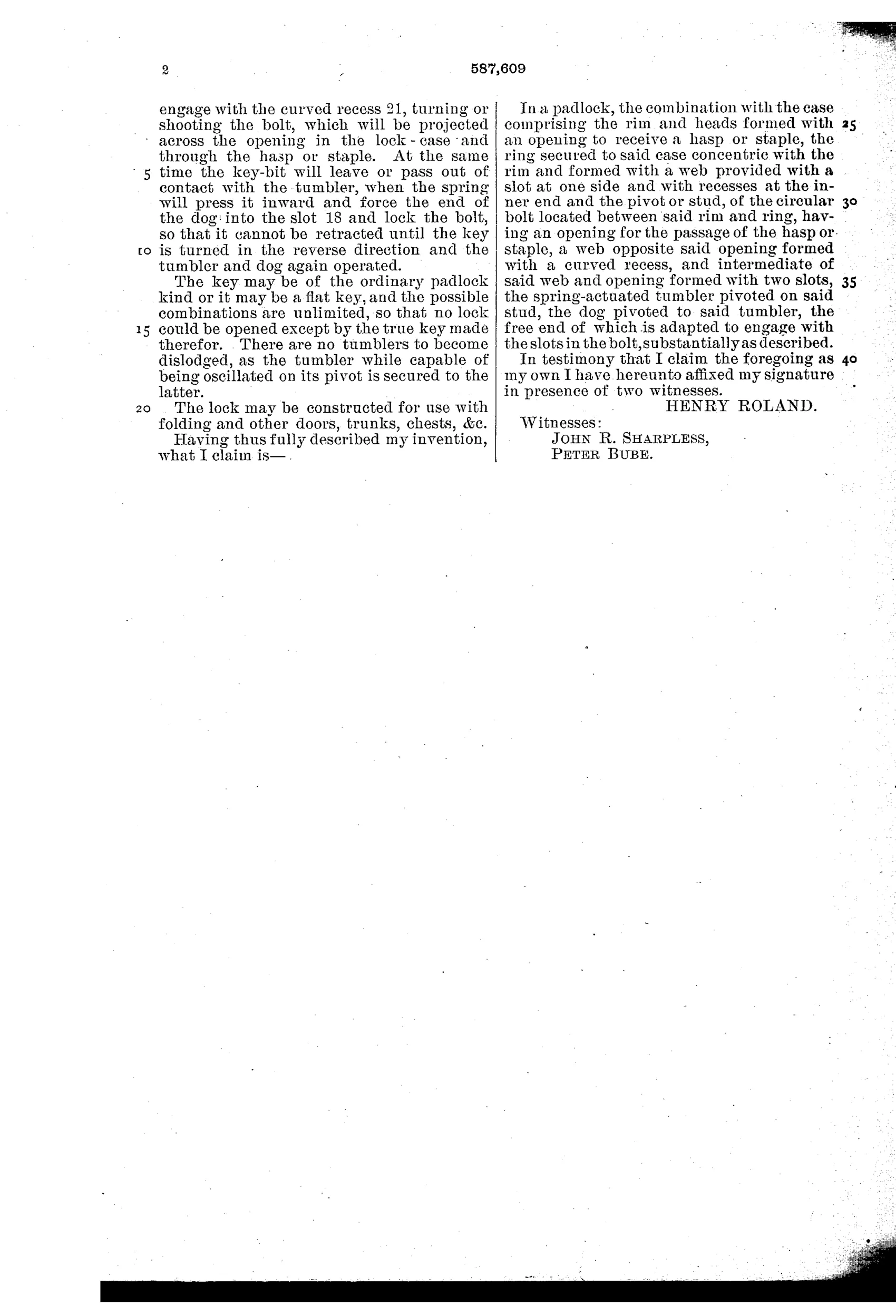
“In a padlock, the combination with the case comprising the rim and heads formed with an opening to receive a hasp or staple, the ring secured to said case concentric with the rim and formed with a web provided with a slot at one side and with recesses at the inner end and the pivot or stud, of the circular bolt located between said rim and ring, having an opening for the passage of the hasp or staple, a web opposite said opening formed with a curved recess, and intermediate of said web and opening formed with two slots, the spring-actuated tumbler pivoted on said stud, the dog pivoted to said tumbler, the free end of which is adapted to engage with the slots in the bolt, substantially as described.”
In plain English: A padlock where a rotating circular bolt inside a ring, controlled by a spring-loaded tumbler and pivoted dog engaging slots in the bolt, locks and unlocks a hasp passing through the case.
⚿ In the inventor’s words
“There are no tumblers to become dislodged, as the tumbler while capable of being oscillated on its pivot is secured to the latter.”— Henry Roland, from the specification
Fate unknown
No known manufacturer took up this design and no marked specimen is documented; a surviving example of this distinctive circular-bolt case would settle it.
⚿ Commentary
Most padlocks of 1897 shot a straight bolt or dropped a ball into a notch on the shackle. Henry Roland instead made the bolt itself a segment of a circle, riding in the annular channel between the case rim and an inner ring, swinging across the hasp opening like a shutter. It's the same instinct that later gave us the rotating-disc mechanisms of the 20th century: use the round case shape you already have instead of fighting it.
The drawing rewards a slow look. Figures 1 and 2 show the two states — bolt withdrawn, bolt shot — and the working parts are just three pieces: the segmental bolt with its two slots, a spring tumbler pivoted on a stud, and a small dog hung off the tumbler whose nose drops into one slot or the other. The key bit rides in a curved recess in the bolt's web, so one turn both lifts the dog and sweeps the bolt around. Figures 5 through 8 are honest manufacturing drawings — sections through the bolt and the assembled case — which suggests Roland was thinking about how a foundry would actually stack these parts.
The weakness is the same as any single-tumbler lock: security lives entirely in the key bit's shape, and a bent wire could probably work that dog loose. Roland's own boast — 'no tumblers to become dislodged' — is really an admission that there's only one. It's a tidy, buildable dead end: mechanically sound, but offering nothing the lever-tumbler and pin-tumbler crowds weren't already doing better.
Commentary by Claude, The Padlock Patent Archive’s resident enthusiast