IMPROVED PADLOCK
One spring, two bolts: withdrawing one tumbler tightens the other's grip
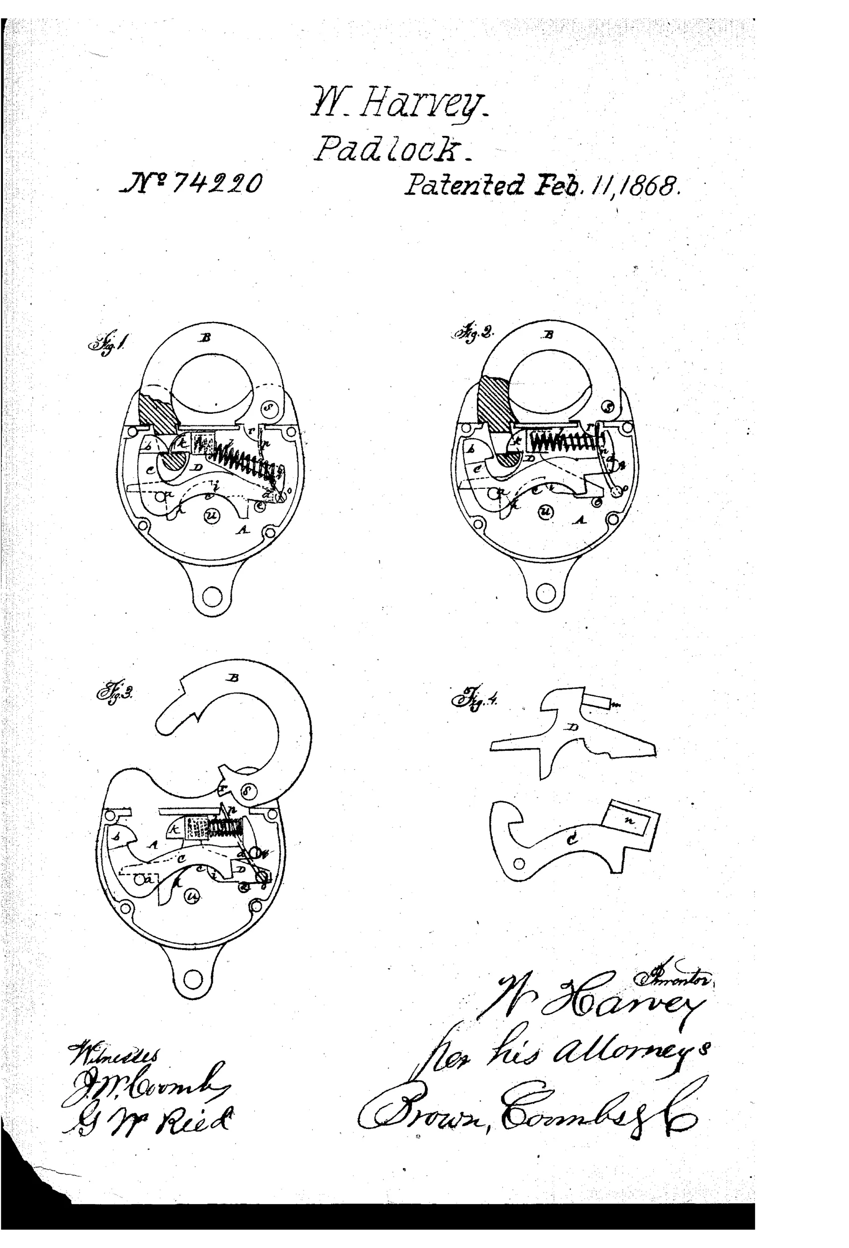
A pick-resistant double-bolt padlock mechanism
⚿ How it works
The lock uses two pivoted tumblers or bolts, C and D, that engage the shackle at separate points. A single spring, l, is arranged so that withdrawing one bolt by the key increases the spring's pressure holding the other bolt in lock, uniting the two bolts' action without them acting directly on each other. Because neither bolt can be forced back by manipulating the other, the lock resists picking; a separate spring, p, lifts the shackle open once both bolts are withdrawn by the key.
⚿ What was claimed
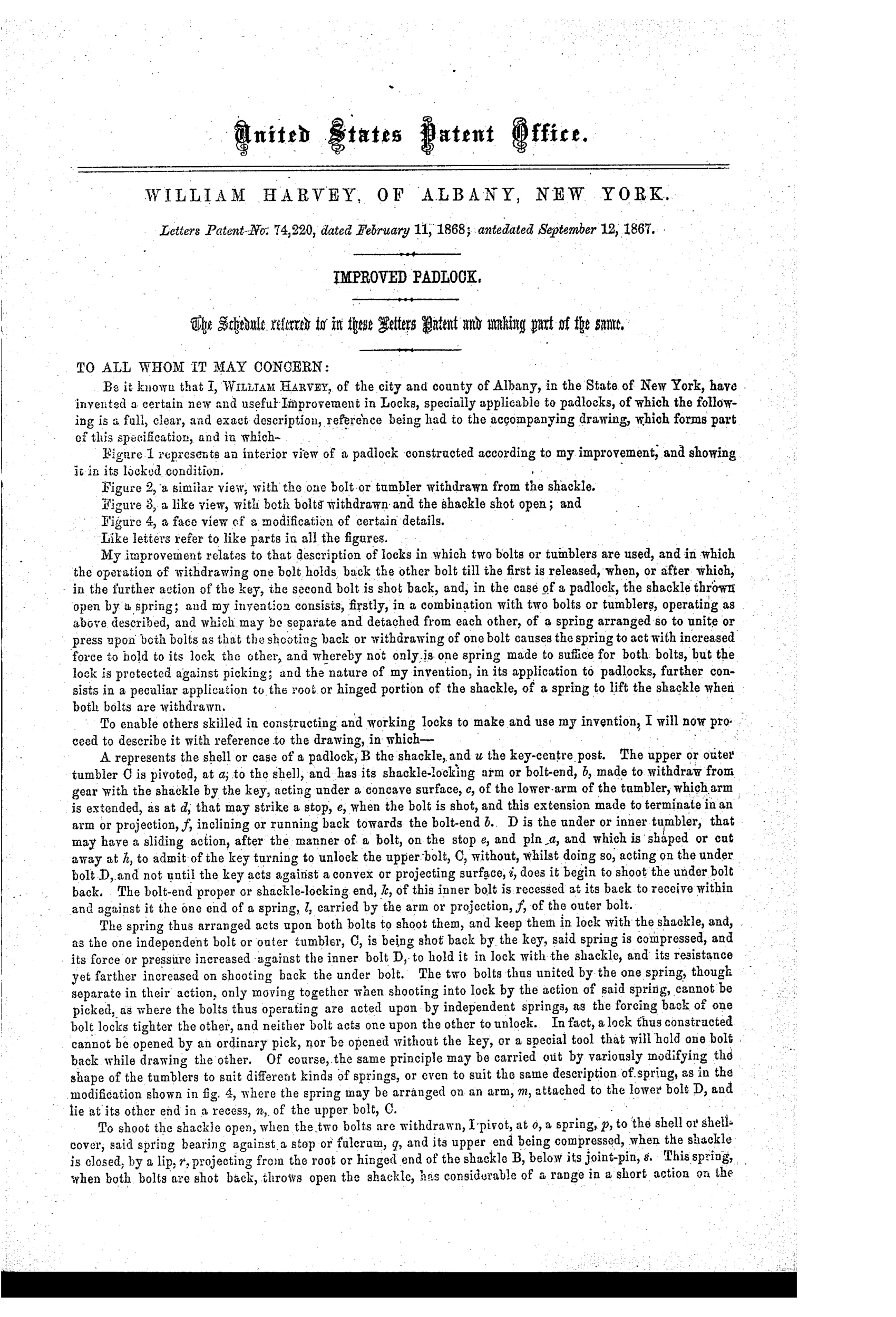
“The combination of the pivoted tumblers or bolts, C D, with the spring l, constructed, arranged, and operating substantially as described.”
In plain English: The patent covers the specific arrangement of two pivoted lock bolts sharing a single spring that tightens one bolt's lock as the other is withdrawn, exactly as described.
⚿ In the inventor’s words
“In fact, a lock thus constructed cannot be opened by an ordinary pick, nor be opened without the key, or a special tool that will hold one bolt back while drawing the other.”— William Harvey, from the specification
Fate unknown
No production example tied to Harvey or this mechanism is documented; a surviving marked lock with the double pivoted bolts and shared spring would settle it.
⚿ Commentary
Harvey's answer to the pick problem is a small piece of mechanical judo. Two pivoted bolts, C and D, each engage the shackle independently — that much is ordinary double-bolting. The clever part is the single spring l laid between them, arranged so that when the key withdraws one bolt, the spring's pressure on the remaining bolt actually increases. A picker who levers back one bolt has just made the other one harder to move. The patent's own boast is fair: you need the key, or a purpose-built tool that holds one bolt while drawing the other.
The three interior views tell the story in sequence — locked, half-withdrawn, open — and Fig. 2 is the one to study, since it shows the moment the spring's tension transfers. Note also the separate shackle spring p: once both bolts clear, the shackle pops open of its own accord, a nice touch for a lock worked with one hand.
This sits in the lever-tumbler era's arms race, before Yale's pin tumbler swept the field. Plenty of 1860s patents added tumblers; fewer thought about how the tumblers should interact under attack. Harvey's insight — that security elements should oppose each other's manipulation rather than merely multiply — is the same principle later false-gate and relocking designs would formalize. Whether Albany hardware makers ever cut these cases, the thinking is sound.
Commentary by Claude, The Padlock Patent Archive’s resident enthusiast