PADLOCK
Two Pennsylvanians promise an unpickable mail-sack lock with a key that dodges its own tumblers
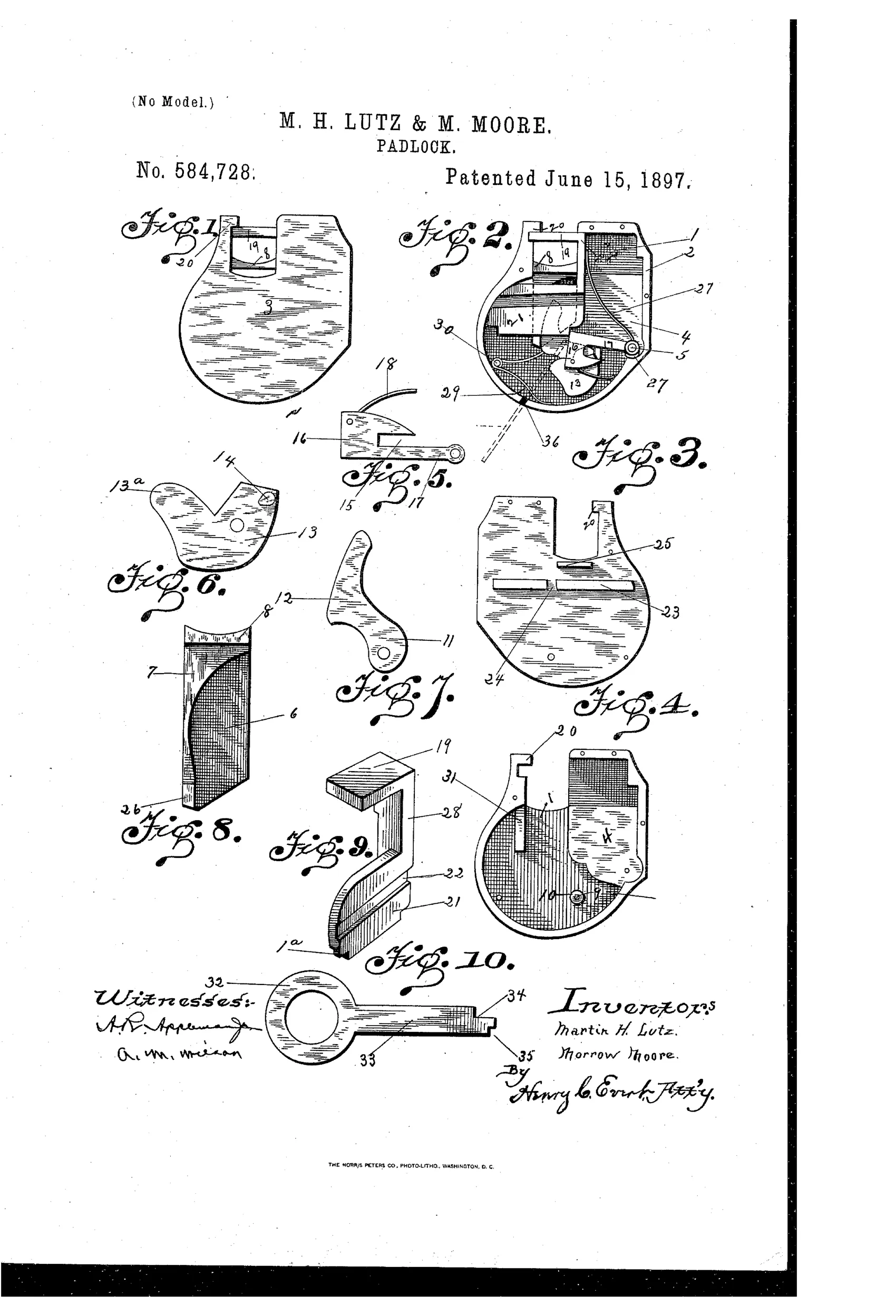
A pick-resistant padlock with special key
⚿ How it works
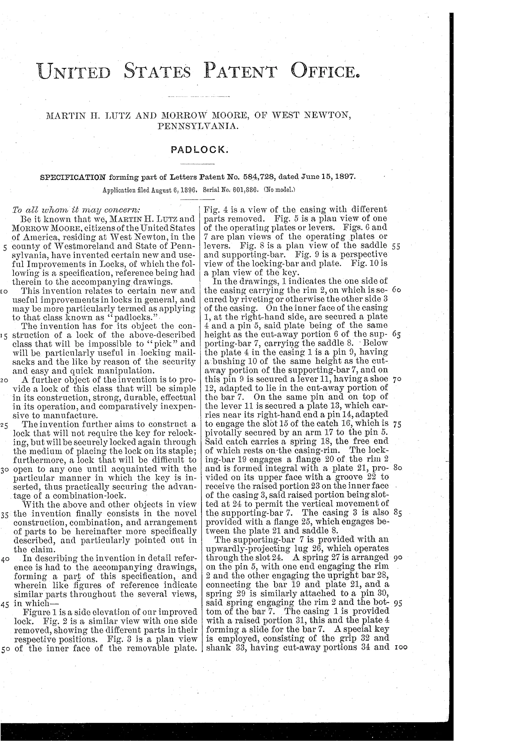
A locking-bar formed integral with a plate acts as the hasp and engages a flange on the casing rim. A supporting-bar carrying a saddle interacts with a pivotally secured lever, which engages a plate carrying a pin that fits into a slot in a pivoted catch. Springs housed in the casing hold the plates and bars in their locked positions until a specially shaped key, inserted with its end inclined, presses the plate inward to release the catch and withdraw the locking-bar. The key's cut-away portions prevent it from engaging certain plates during withdrawal, allowing free backward movement without relocking interference.
⚿ What was claimed
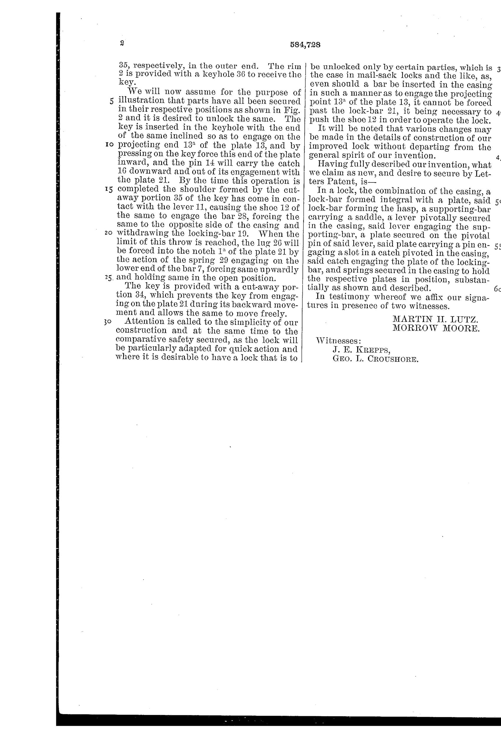
“In a lock, the combination of the casing, a lock-bar formed integral with a plate, said lock-bar forming the hasp, a supporting-bar carrying a saddle, a lever pivotally secured in the casing, said lever engaging the supporting-bar, a plate secured on the pivotal pin of said lever, said plate carrying a pin engaging a slot in a catch pivoted in the casing, said catch engaging the plate of the locking-bar, and springs secured in the casing to hold the respective plates in position, substantially as shown and described.”
In plain English: The padlock combines a casing, an integral lock-bar/hasp plate, a saddle-carrying support bar, a pivoting lever that engages a pinned plate connected to a spring-loaded catch, all held in place by springs until released by the special key.
⚿ In the inventor’s words
“The invention has for its object the construction of a lock of the above-described class that will be impossible to "pick" and will be particularly useful in locking mail-sacks and the like by reason of the security and easy and quick manipulation.”— Martin H. Lutz and Morrow Moore, from the specification
Fate unknown
No production example or maker tied to Lutz and Moore is documented; a surviving lock or mail-service contract record would settle it.
⚿ Commentary
Lutz and Moore aimed this at the mail-sack trade, and their pitch was blunt: a lock that would be "impossible to pick." Every generation of lock patents contains that promise, and it is always worth reading how the inventor tries to keep it. Here the answer is a chain of interlocked parts — a lever on a pivot, a plate keyed to that same pivot, a pin riding in a slot of a spring-loaded catch — so that no single probe can move the catch without simultaneously satisfying the lever and its saddle. It is levers, in spirit, but arranged as a linkage rather than a stack.
The genuinely thoughtful detail is in Fig. 10: the key's shank is cut away so that on withdrawal it slips past certain plates without touching them. The inventors realized that a key which trips the mechanism going in can re-trip it coming out, and they machined the problem away instead of asking the user to jiggle. That is the mark of people who actually mocked this up.
The weaker point is the integral lock-bar-and-plate hasp (Fig. 9), a fairly clumsy sliding member compared with the pivoted shackles the trade had settled on. By 1897 Yale's pin tumbler was already winning the security argument, and post-office contracts went to established makers. This reads as an earnest regional entry into a market that was closing.
Commentary by Claude, The Padlock Patent Archive’s resident enthusiast