IMPROVEMENT IN PADLOCKS
Three moving parts must dance in sequence before this bolt lets go
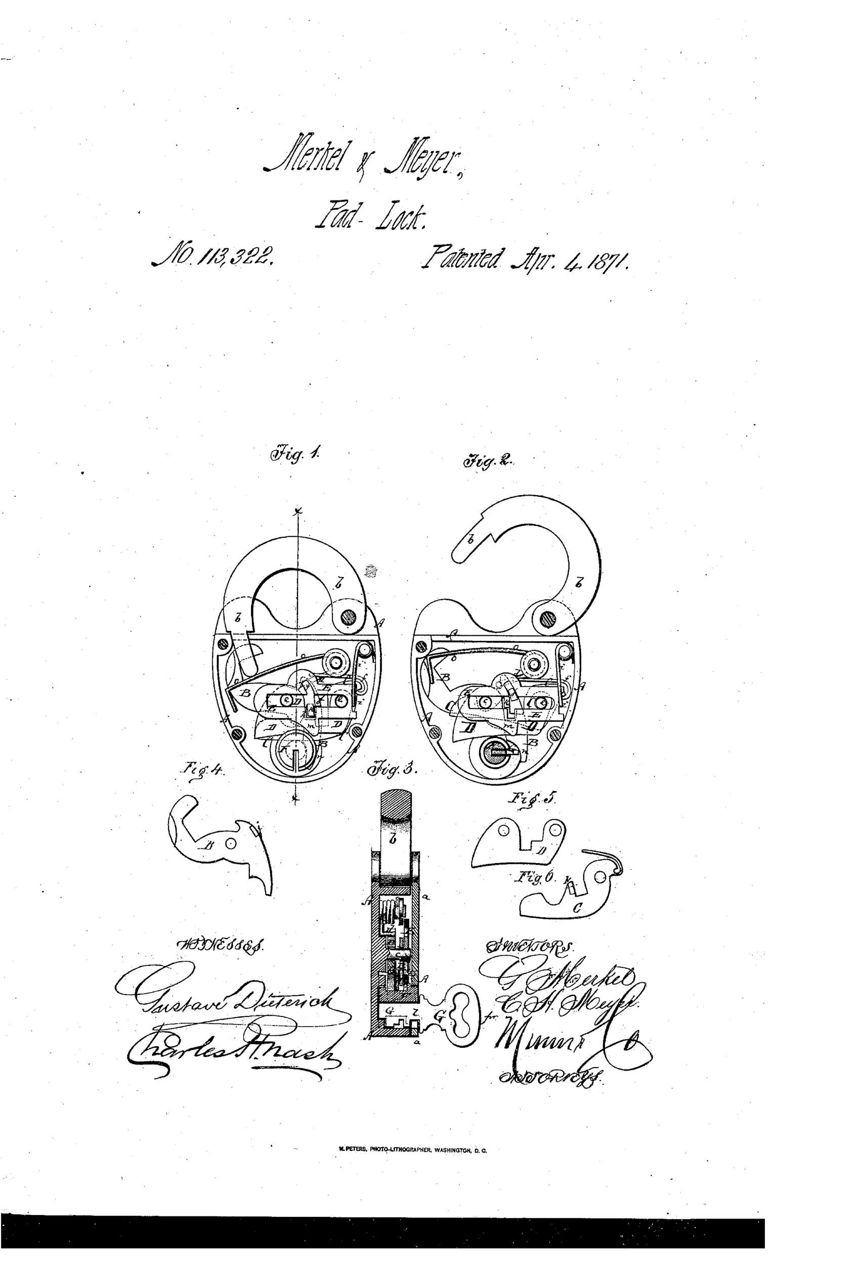
Pick-resistant padlock with swinging bolt mechanism
⚿ How it works
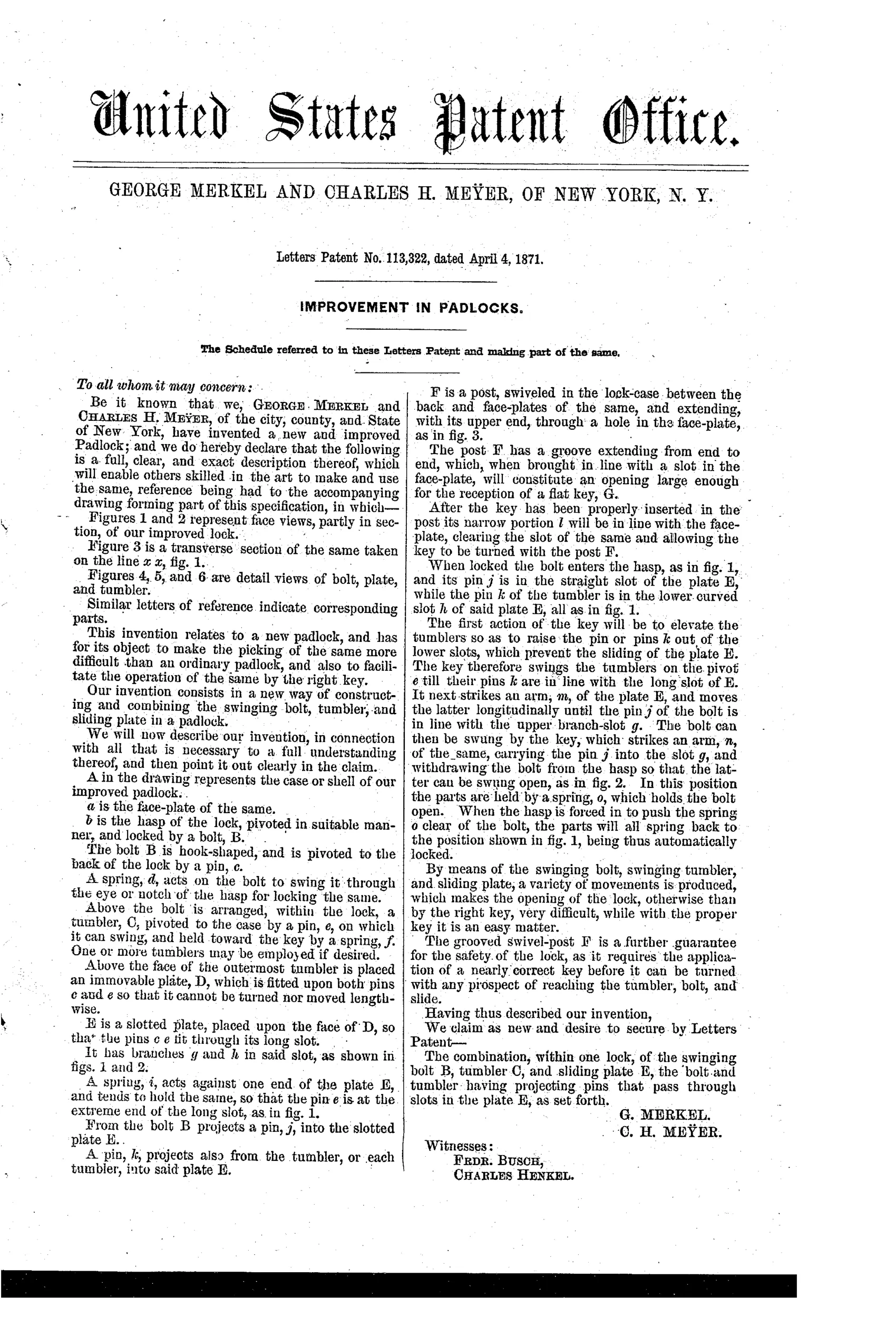
A hook-shaped bolt B pivots on a pin c and is spring-loaded to swing through the hasp notch for locking. A tumbler C pivots on a separate pin e and is held toward the key by a spring, with pins on both the bolt and tumbler projecting into slots of a sliding plate E. Turning the key first raises the tumbler's pin out of a lower curved slot, then shifts the slotted plate E longitudinally, and finally swings the bolt's pin into an upper slot to withdraw the bolt from the hasp. A grooved swivel-post F requires a nearly correct key shape before it can even be turned to reach the internal bolt and tumbler mechanism.
⚿ What was claimed
“The combination, within one lock, of the swinging bolt B, tumbler C, and sliding plate E, the bolt and tumbler having projecting pins that pass through slots in the plate E, as set forth.”
In plain English: The patent claims the specific combination of a swinging bolt, a swinging tumbler, and a sliding slotted plate, where pins on the bolt and tumbler both engage slots in that plate to control locking and unlocking.
⚿ In the inventor’s words
“The grooved swivel-post F is a further guarantee for the safety of the lock, as it requires the application of a nearly correct key before it can be turned with any prospect of reaching the tumbler, bolt, and slide.”— George Merkel and Charles H. Meyer, from the specification
Fate unknown
No marked production example of this Merkel & Meyer design is documented; a surviving lock matching the slotted-plate internals would settle it.
⚿ Commentary
Merkel and Meyer's answer to lock-picking is choreography. The hook-shaped bolt and the tumbler each carry a pin, and both pins ride in slots cut into a sliding plate. A correct key performs three acts in one turn: lift the tumbler's pin clear of its curved slot, shove the plate along its track, and only then swing the bolt's pin into the upper slot to pull the hook out of the hasp. Get any step out of order — as a pick working blind almost certainly would — and the plate simply refuses to move.
The detail the drawing rewards is the grooved swivel-post F, visible in the Fig. 3 cross-section. It's a gatekeeper: a key with the wrong profile can't even rotate far enough to touch the working parts. The inventors say so plainly, promising that a 'nearly correct key' is needed 'before it can be turned with any prospect of reaching the tumbler, bolt, and slide.' That's warded security layered on top of the slotted-plate sequence — belt and suspenders, 1871 style.
Where does it sit? Squarely in the pre-Yale scramble, when inventors piled up interlocking levers and slides to buy security through complexity. The pin tumbler would soon make this whole family look baroque. But as a mechanism it's honest work: nothing here defies manufacture, and the sequential-slot idea is genuinely harder to defeat than a single spring lever.
Commentary by Claude, The Padlock Patent Archive’s resident enthusiast