PADLOCK
Slaymaker's own name on the patent, with a spring that hugs the shackle
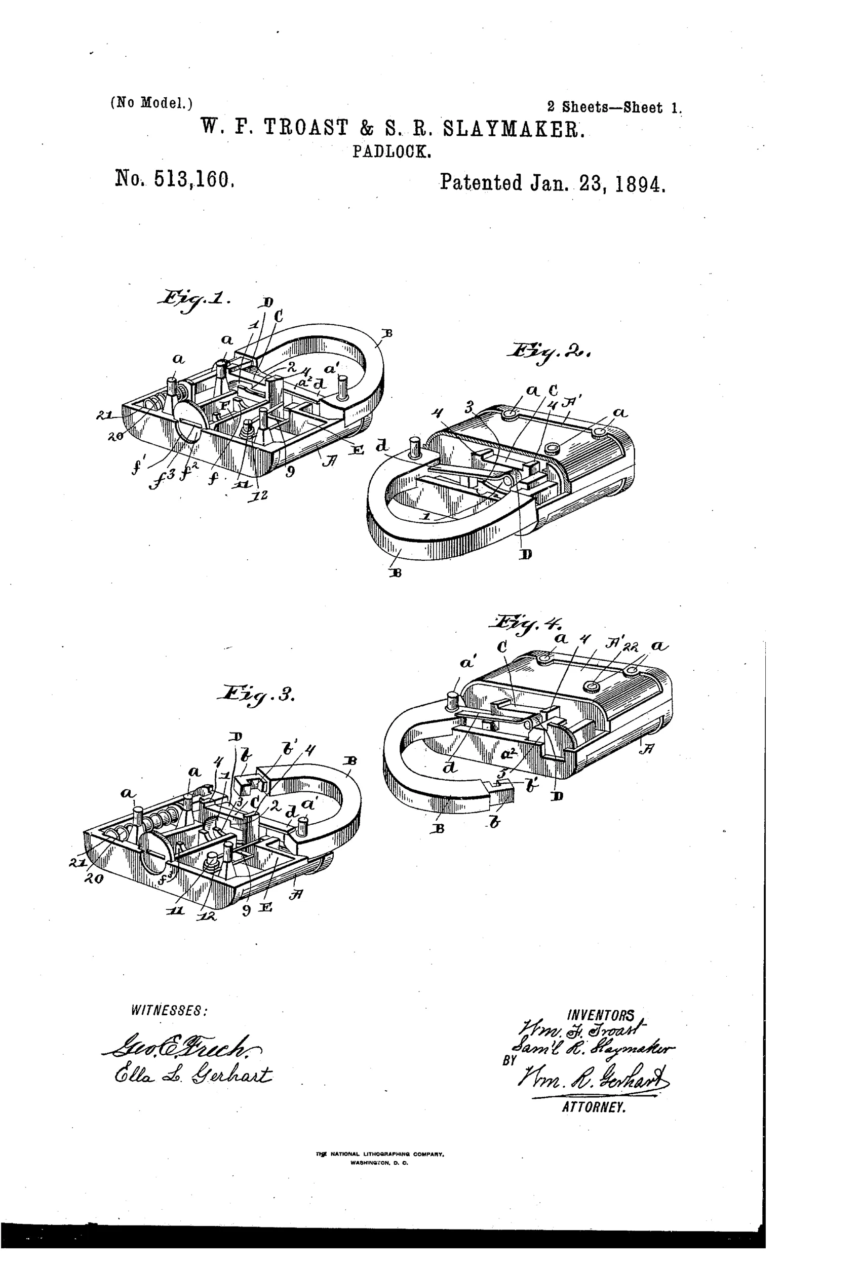
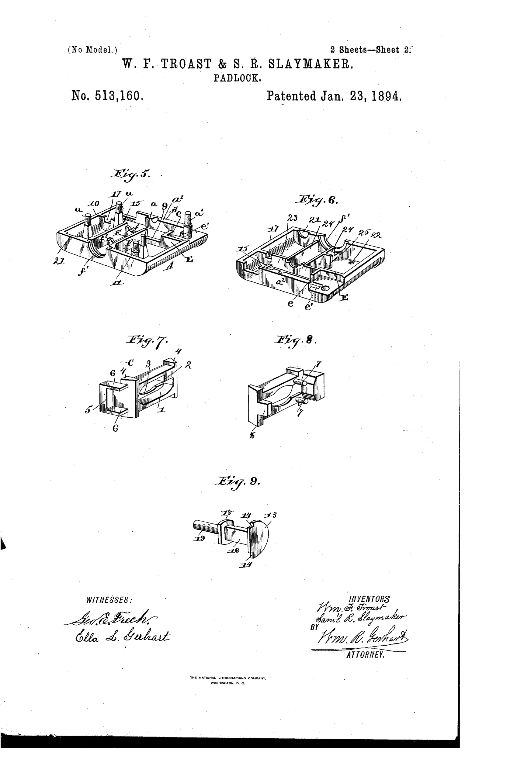
Improved shackle padlock with locking bolt
⚿ How it works
A U-shaped shackle has one end pivoted in the case and the other end, reduced and notched, swings into a channel to be secured by a sliding locking bolt. The bolt carries a tongue with lips that embrace the fixed end of the shackle and a V-shaped or bent spring that abuts and laps the fast end as the bolt disengages, preventing transverse motion of the swinging shackle end. A flat key passes through a key-guide and key-hole guard, engaging a shoulder in an oval opening in the bolt to force it back against a coil spring, while a separate spring-loaded plunger with a semicircular head pushes the shackle open once released. Registering walls and recesses in the bisected case body and cap guide the bolt, spring, and plunger and exclude foreign matter from the shackle space.
⚿ What was claimed
“In a padlock, the combination, with a bolt movable between the "fast" and swinging ends of the shackle, of a spring attached thereto having the vibrating end adapted to abut against the "fast" end of the shackle when the bolt is engaged with the swinging end thereof and to lap said "fast" end when the bolt is disengaged from the swinging end of the shackle, substantially as and for the purpose specified.”
In plain English: The lock uses a movable bolt with an attached spring that presses against the fixed shackle end when locked and wraps around it when the bolt is withdrawn, keeping the shackle from shifting sideways.
⚿ In the inventor’s words
“The objects of the invention are, first, to guard more thoroughly against the surreptitious opening of the lock than is done in the padlocks now in use; and second, to prevent transverse motion of the swinging end of the shackle when locked in the case.”— William F. Troast and Samuel R. Slaymaker, from the specification
Manufactured and sold
A Slaymaker in-house design assigned to Slaymaker, Barry & Co., whose pivoted-shackle flat-key padlocks of this era were produced and sold in quantity.
⚿ Commentary
This is a house patent in the best sense: Samuel R. Slaymaker co-invented it and assigned it straight to Slaymaker, Barry & Co. of Lancaster — the firm that would become one of the workhorse names in American padlocks. So the document reads less like a hopeful inventor's flyer and more like a factory solving its own production problems on paper.
The mechanical target is modest but real: pivoted-shackle padlocks of the day tended to rattle. The swinging end of the shackle could be wiggled sideways, which both felt cheap and gave a picker something to work with. The clever bit is the V-shaped spring riding on the sliding bolt. When the bolt is home, the spring abuts the fixed shackle end and braces everything tight; when the key drives the bolt back, the spring laps around that fixed end and keeps steering the free end into its channel. One spring, two jobs, no extra parts. Add the spring-loaded plunger that pops the shackle open when released — a nice touch of one-handed convenience — and the registering walls cast into the bisected case that both guide the parts and seal out grit.
Nothing here is revolutionary; the flat key and warded approach were already old news against Yale's pin tumblers. But as a piece of manufacturable, dirt-tolerant, low-cost hardware design, it shows exactly why Slaymaker locks sold by the crate for decades.
Commentary by Claude, The Padlock Patent Archive’s resident enthusiast