PADLOCK.
The 1888 padlock that put Slaymaker's name on a patent grant
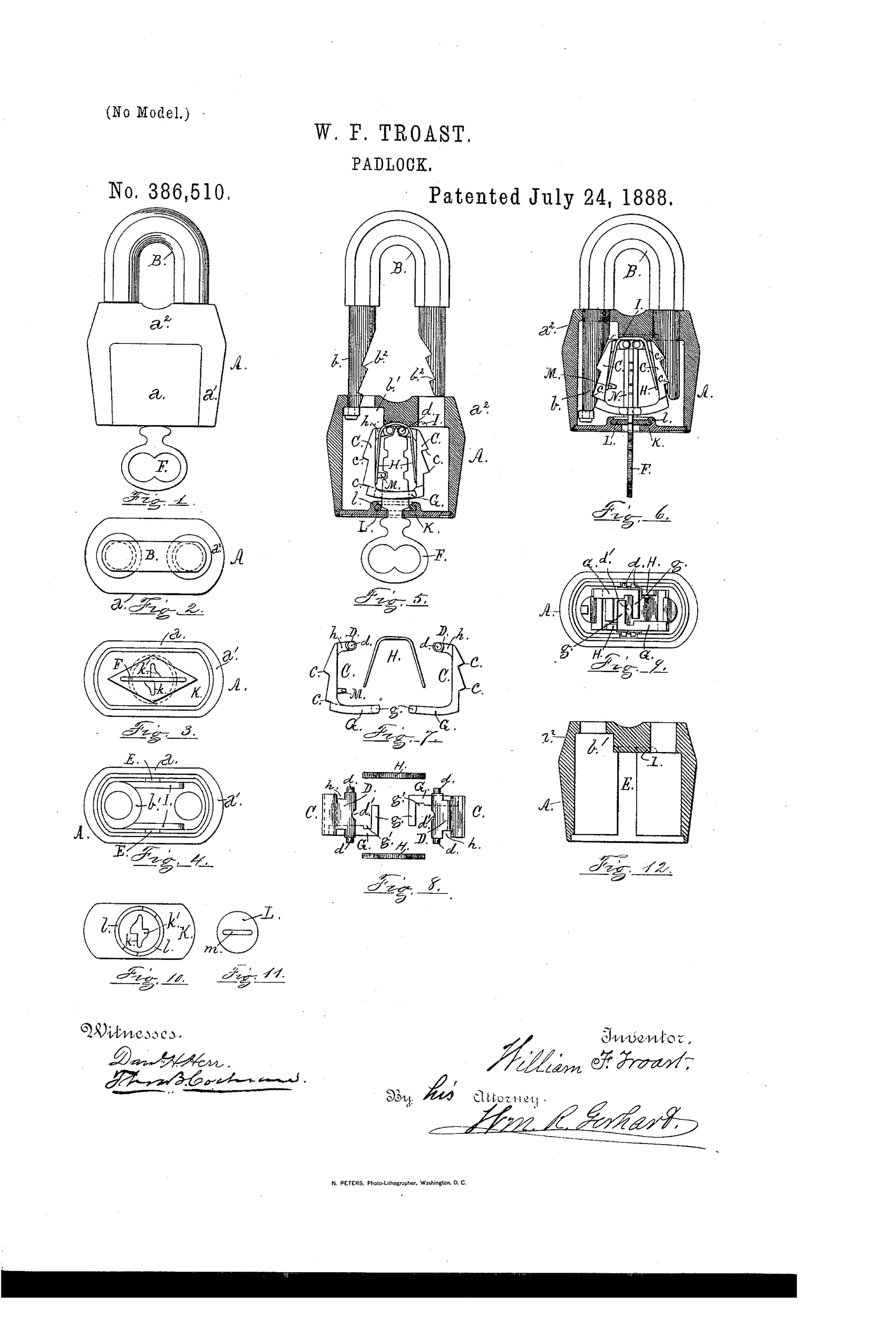
A u-shaped shackle padlock with tumblers
⚿ How it works
The padlock uses a U-shaped shackle with notches in both arms, held in place by two tumbler-plates journaled vertically in the case. Curved springs bear against the inner faces of the tumblers, forcing their lower vibrating ends apart so projections engage the shackle notches automatically when the shackle is pushed in. The tumblers have interlocking rectangular arms at their lower ends that form a keyhole opening; turning the key draws these arms together, disengaging the tumblers from the shackle to unlock it. A guard-plate with a slot covers the key recesses when the key is removed and rotates with the key when turned.
⚿ What was claimed
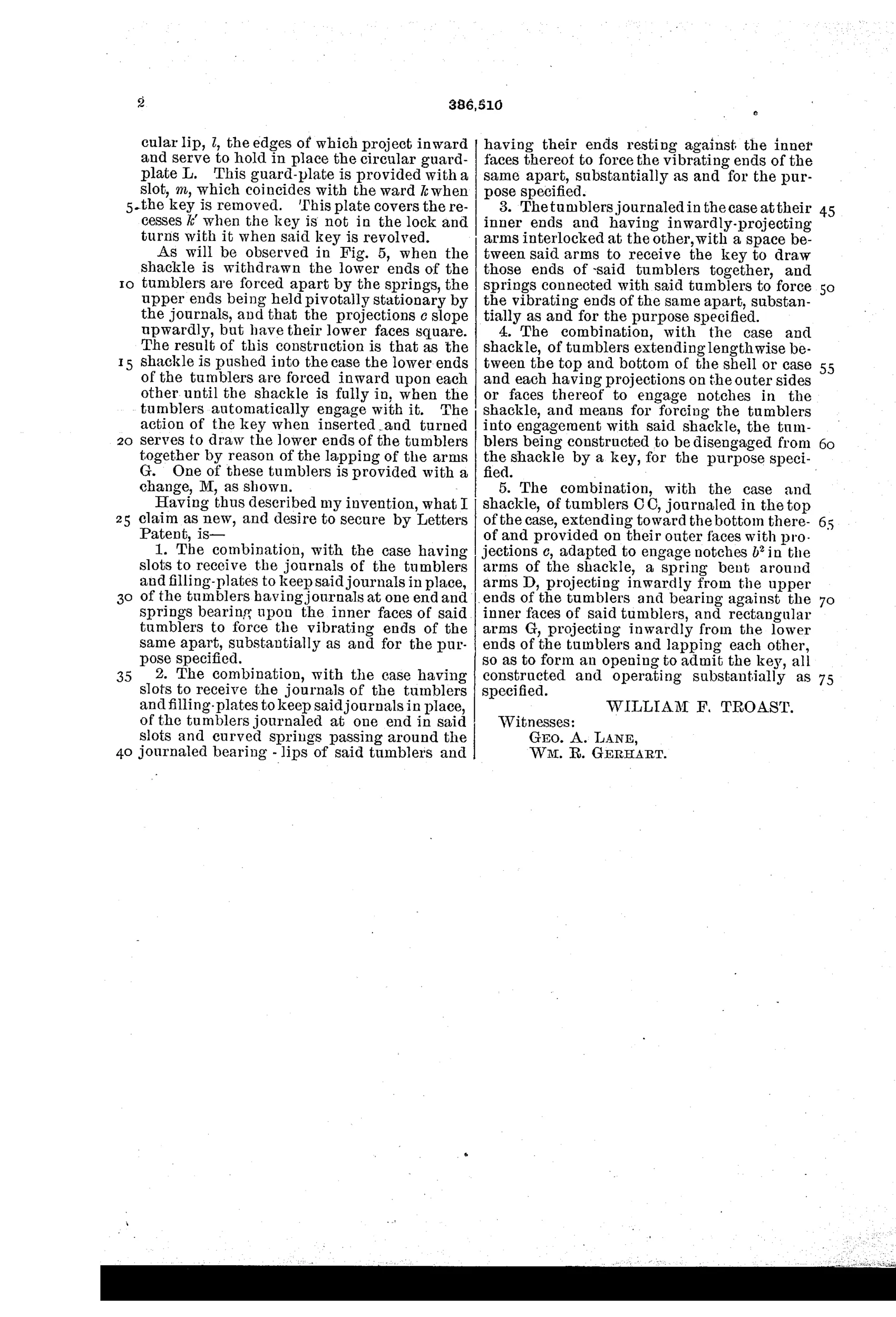
“The combination, with the case and shackle, of tumblers C C, journaled in the top of the case, extending toward the bottom thereof and provided on their outer faces with projections c, adapted to engage notches b2 in the arms of the shackle, a spring bent around arms D, projecting inwardly from the upper ends of the tumblers and bearing against the inner faces of said tumblers, and rectangular arms G, projecting inwardly from the lower ends of the tumblers and lapping each other, so as to form an opening to admit the key, all constructed and operating substantially as specified.”
In plain English: The lock combines a case and shackle with spring-loaded tumbler plates that have projections engaging notches in the shackle arms, and interlocking lower arms that form a keyhole opening to admit the key for unlocking.
⚿ In the inventor’s words
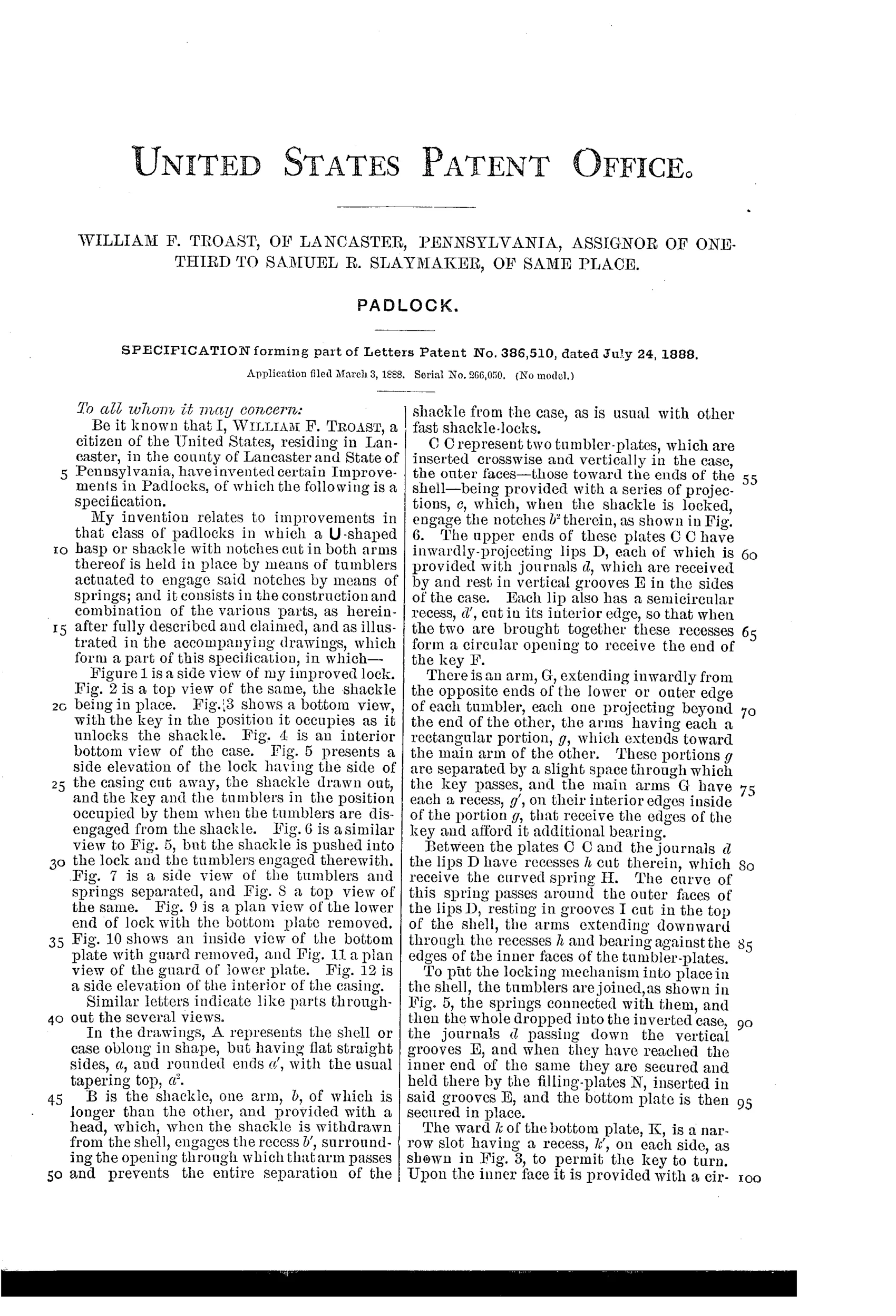
“The result of this construction is that as the shackle is pushed into the case the lower ends of the tumblers are forced inward upon each other until the shackle is fully in, when the tumblers automatically engage with it.”— William F. Troast, from the specification
Fate unknown
The Slaymaker assignment strongly suggests commercial intent, but no specimen matching this exact tumbler arrangement is documented to me; a marked Lancaster-made example would settle it.
⚿ More by William F. Troast
- PADLOCK. (1889)
⚿ Commentary
The mechanism here is honest and economical: two flat tumbler plates hang from pivots at the top of the case, one alongside each arm of the U-shackle. A curved spring wedges their lower ends apart so that projections on their outer faces snap into notches in both shackle legs the moment the shackle is pushed home. That's self-locking — no key needed to close it, which by 1888 was already understood to be what working customers wanted. The key does one job: entering through the bottom, it spreads apart, then squeezes together, the interlocked rectangular arms at the tumblers' feet, pulling both projections out of the notches simultaneously.
Two details in the drawing reward a close look. Figures 7 and 8 show that the tumblers' lower arms lap over each other and themselves form the keyhole — the keyway is not a hole in a plate but a gap between the moving parts. And Fig. 11 shows a rotating guard plate that rides with the key and covers the key recesses when it's withdrawn, a dust shield aimed squarely at outdoor service.
The name to notice is in the assignment: one-third to Samuel R. Slaymaker of Lancaster, the man whose company would become one of the great American padlock houses. Whether this exact double-tumbler layout reached the bench, Troast's patent sits right at the root of that story.
Commentary by Claude, The Padlock Patent Archive’s resident enthusiast