IMPROVEMENT IN PADLOCKS
A circular spring bolt and a disk-stacked keyhole guard against Sierra weather
A padlock with circular bolt and rotating dust cap
⚿ How it works
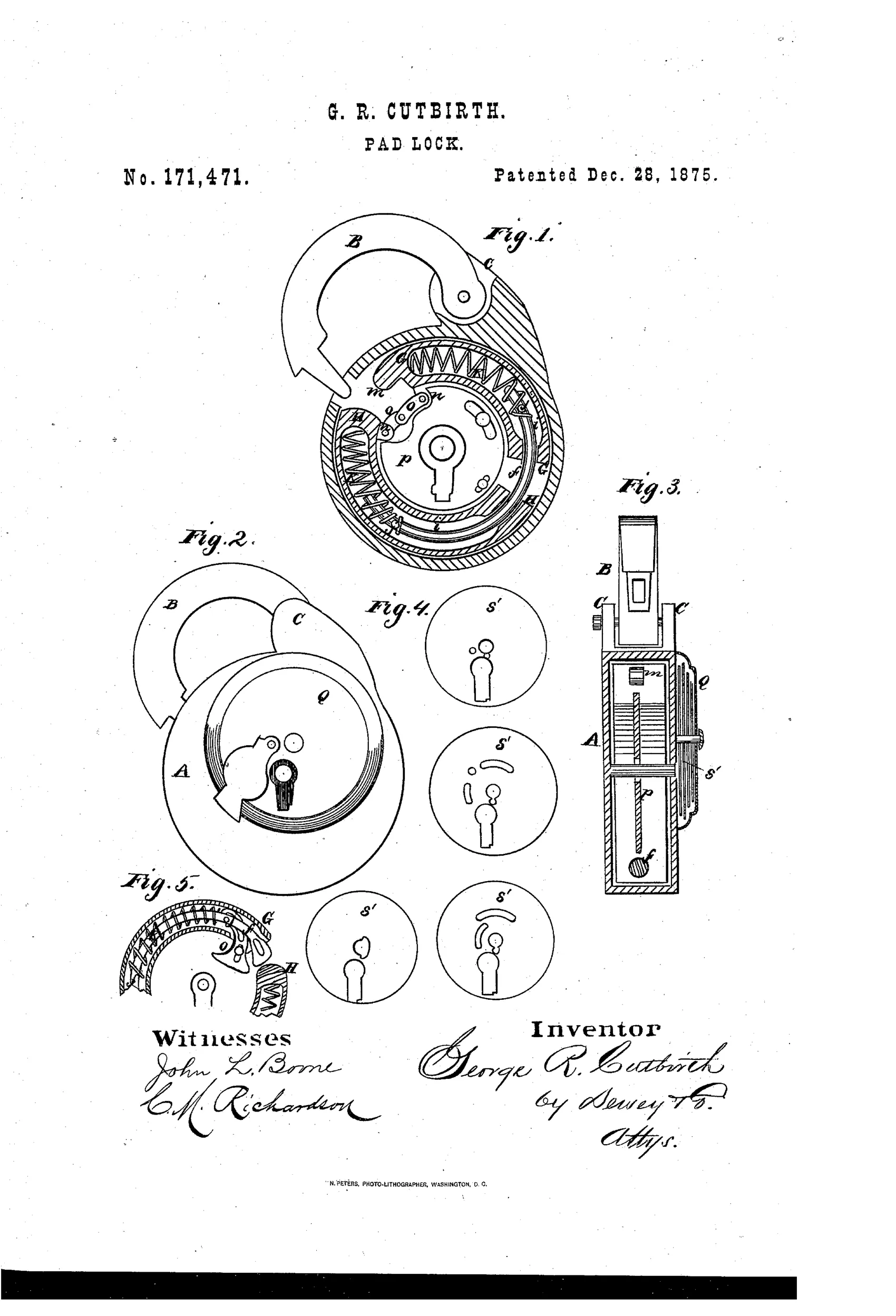
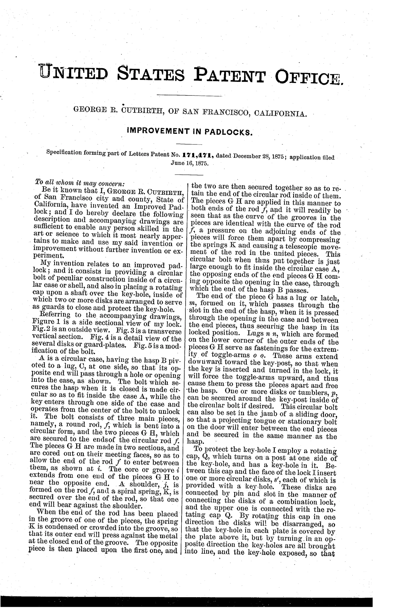
The hasp B pivots on lug C and its free end passes through an opening into the circular case A. Inside the case a circular bolt made of a bent rod f and two hollow end pieces G and H, held apart by spiral springs K, secures the hasp by a latch lug that passes through the hasp slot. Turning the key operates toggle-arms that press the end pieces apart, compressing the springs and freeing the hasp. A rotating cap Q over the keyhole works with a stack of slotted disks s' that must be aligned by turning the cap before the key can enter, guarding the keyhole from dust, snow, or rain.
⚿ What was claimed
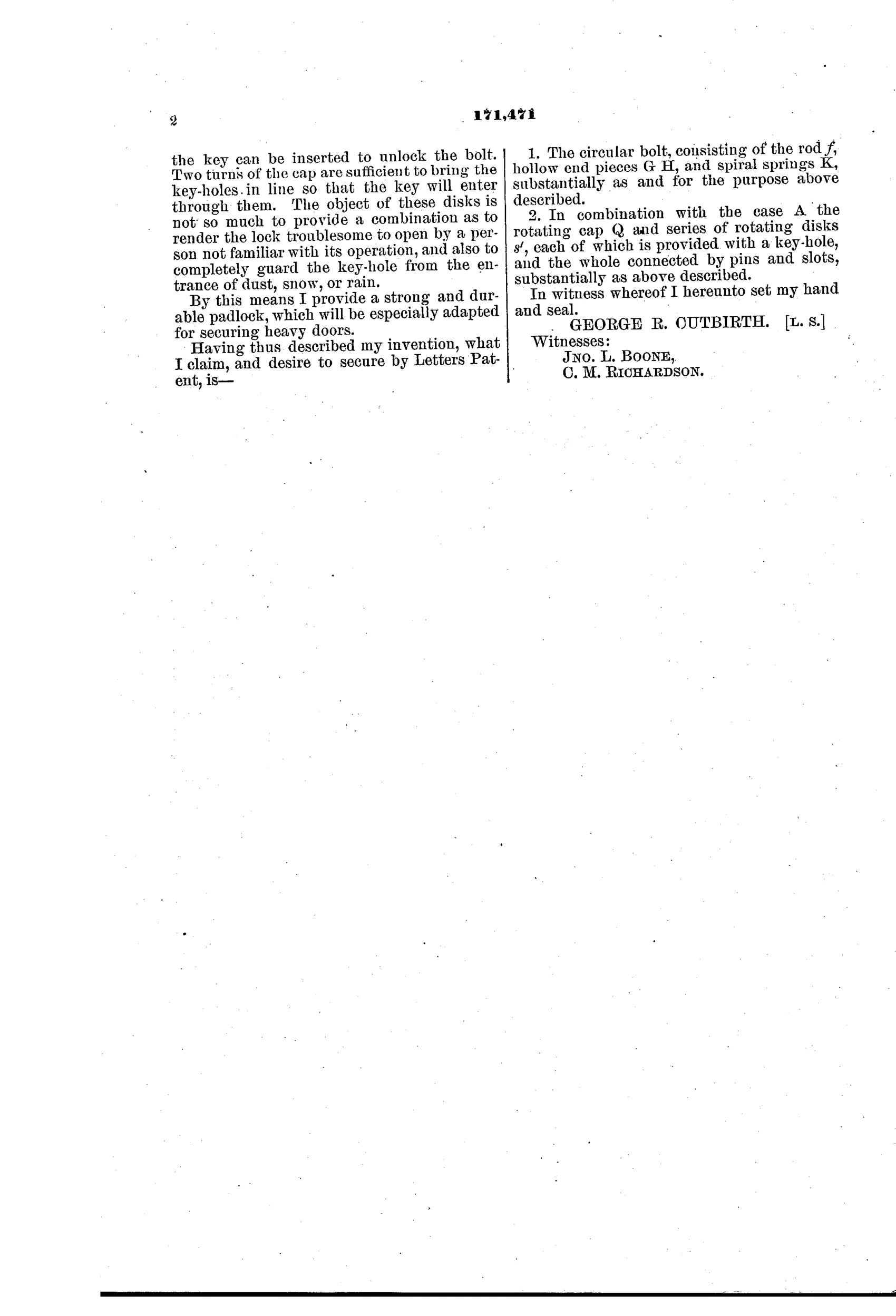
“1. The circular bolt, consisting of the rod f, hollow end pieces G H, and spiral springs K, substantially as and for the purpose above described. 2. In combination with the case A the rotating cap Q and series of rotating disks s', each of which is provided with a key-hole, and the whole connected by pins and slots, substantially as above described.”
In plain English: The lock's core novelty is a circular spring-loaded bolt made of a bent rod and two hollow end pieces, plus a rotating cap with aligned key-holed disks that must be turned into position before the key can be inserted.
⚿ In the inventor’s words
“The object of these disks is not so much to provide a combination as to render the lock troublesome to open by a person not familiar with its operation, and also to completely guard the key-hole from the entrance of dust, snow, or rain.”— George R. Cutbirth, from the specification
Fate unknown
Cutbirth has no known manufacturing tie and the design matches no documented production lock; a surviving marked specimen would settle it.
⚿ Commentary
Cutbirth's lock builds its bolt as a ring: a bent rod with two hollow end pieces, pushed apart by coiled springs so the whole assembly hugs the inside of the round case. The key doesn't throw a bolt in the usual sense — it works toggle-arms that squeeze the ring's ends together against the springs, letting the hasp slip free. Fig. 5 shows he was still tinkering, offering a modified version of the same ring. It's an elegant fit of mechanism to case shape, though a bolt that depends on spring pressure alone to stay locked invites the classic attack of rapping the case to bounce the springs.
The more charming half is the rotating cap Q and its stack of slotted disks, drawn out step by step in Fig. 4. Each disk carries a keyhole; turn the cap and pins-and-slots drag the disks into alignment before the key can enter. Cutbirth is refreshingly honest about it: the disks exist "not so much to provide a combination" as to baffle strangers and, mainly, to seal the keyhole against dust, snow, and rain. That's a working man's concern — a San Francisco inventor thinking about locks left outdoors, not parlor puzzles.
As security it's modest; as weatherproofing it anticipates the shrouded and shuttered keyholes that railroad and outdoor locks would keep chasing for decades. A sincere, slightly over-built entry from the era when padlock architecture was still wide open.
Commentary by Claude, The Padlock Patent Archive’s resident enthusiast