PADLOCK.
An Aspen miner-town answer to the pried-off bottom plate: no rivets to attack
Tamper-resistant padlock with locking internal frame
⚿ How it works
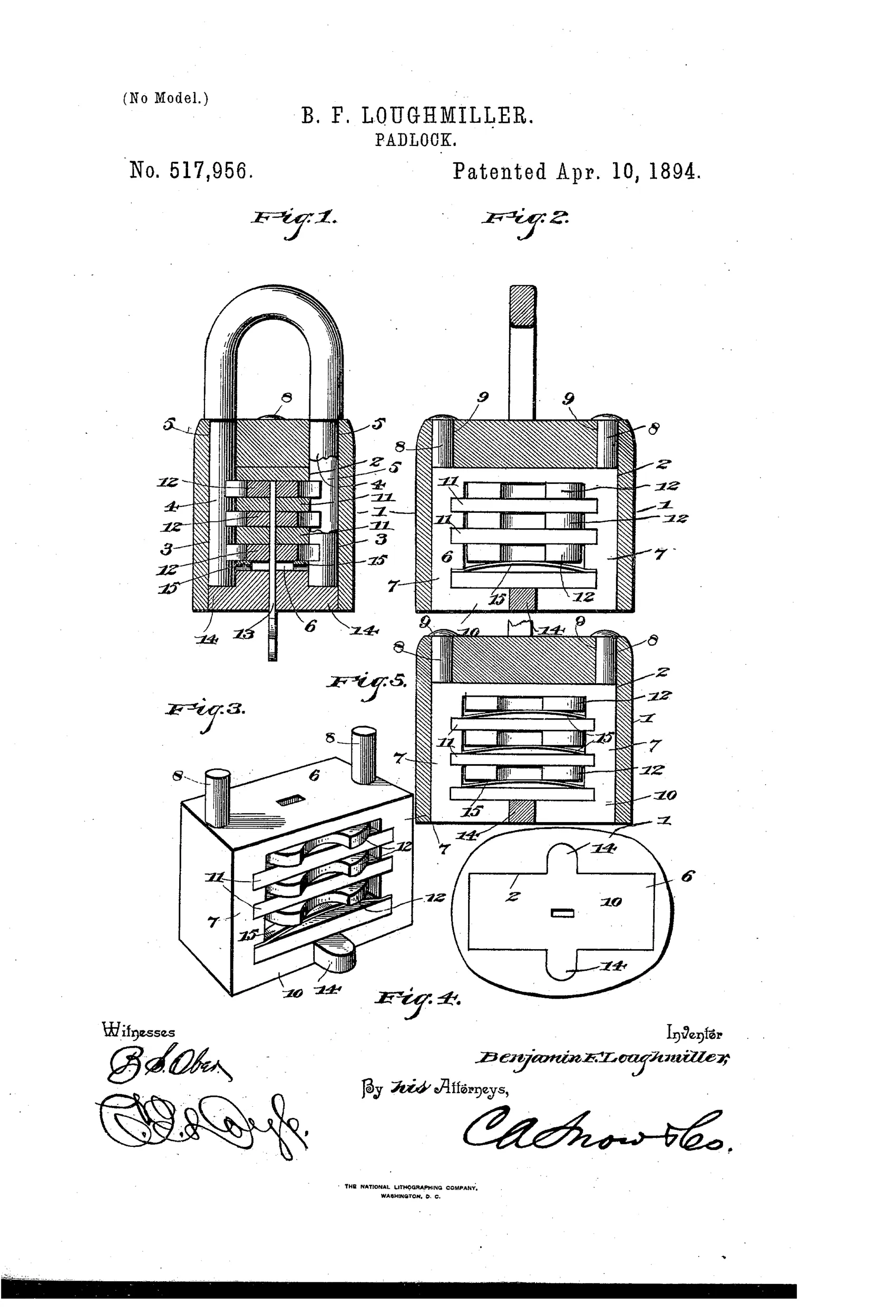
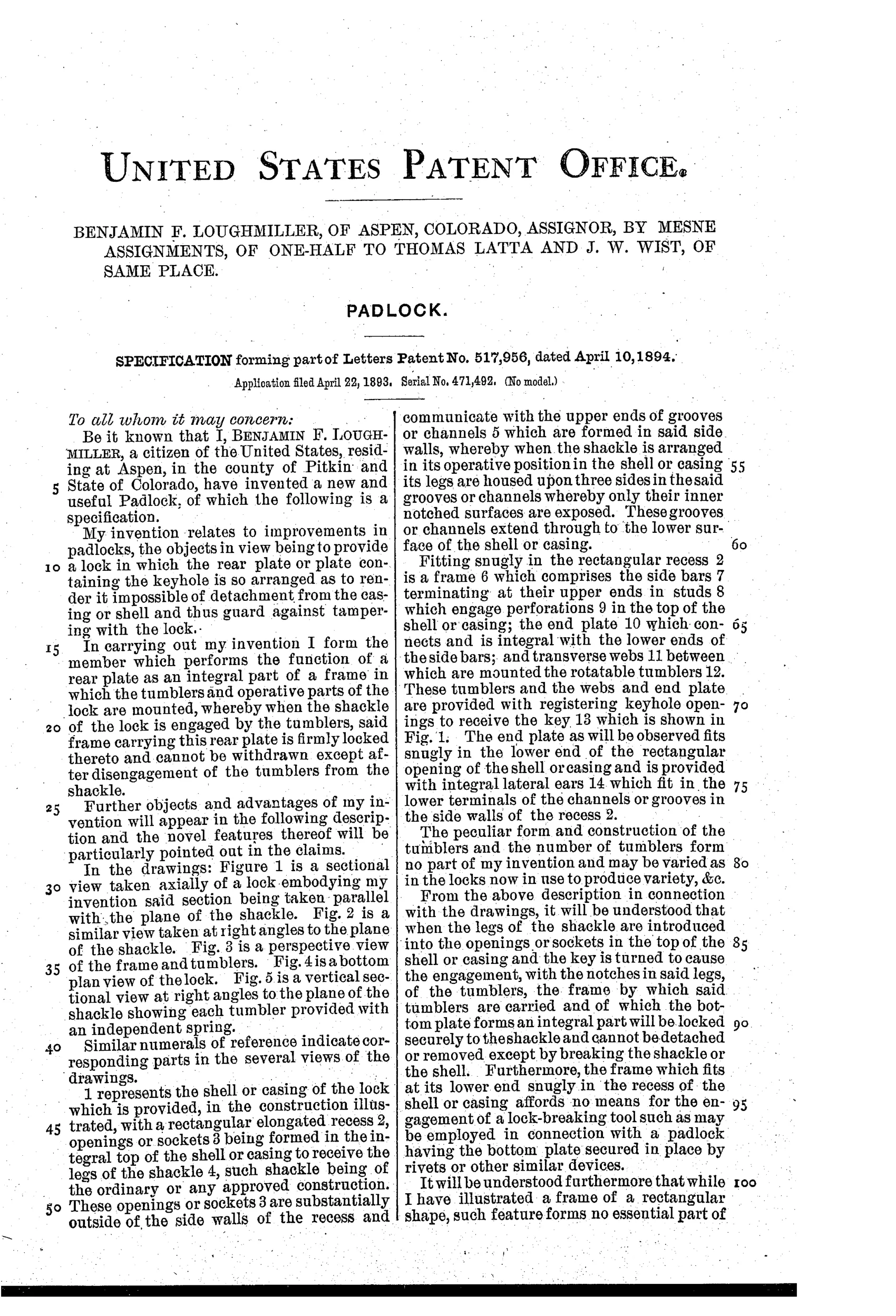
The lock has a hollow shell or casing with a recess into which a separate internal frame fits snugly, this frame carrying side bars, a bottom end plate, transverse webs, and rotatable notched tumblers. The shackle legs enter sockets in the top of the casing and are guided into grooves so that only their notched inner surfaces are exposed to the tumblers. When the key rotates the tumblers, their peripheries engage the notches in the shackle legs, locking the entire frame (with its integral bottom plate) to the shackle so it cannot be withdrawn or detached from the casing. Because the bottom plate is integral with the frame rather than riveted on, the lock cannot be picked apart by breaking the shackle or prying the bottom plate, and tumblers may optionally each have their own spring (Fig. 5) or share a single spring on the bottom tumbler (Figs. 1-3).
⚿ What was claimed
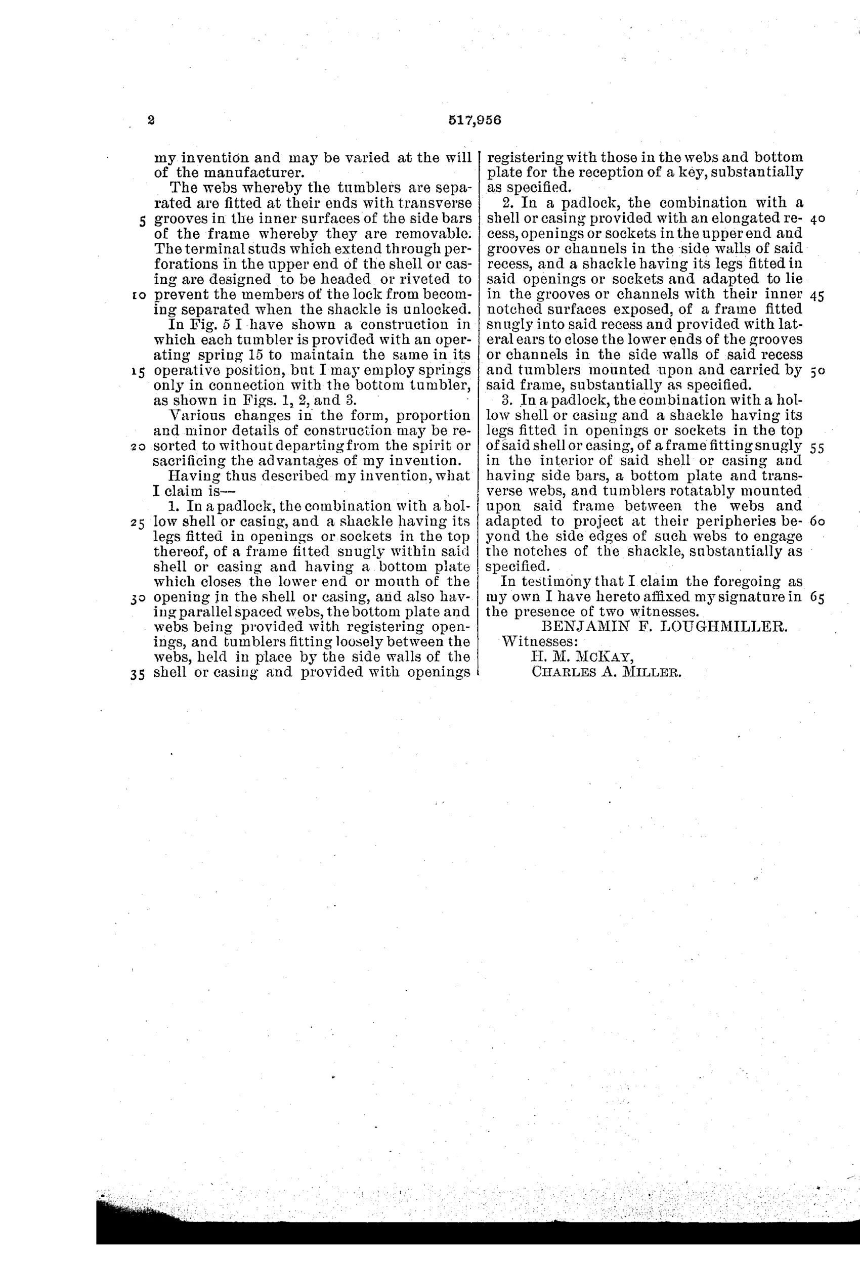
“1. In a padlock, the combination with a hollow shell or casing, and a shackle having its legs fitted in openings or sockets in the top thereof, of a frame fitted snugly within said shell or casing and having a bottom plate which closes the lower end or mouth of the opening in the shell or casing, and also having parallel spaced webs, the bottom plate and webs being provided with registering openings, and tumblers fitting loosely between the webs, held in place by the side walls of the shell or casing and provided with openings registering with those in the webs and bottom plate for the reception of a key, substantially as specified.”
In plain English: The padlock combines a hollow outer casing and a shackle with legs seated in top sockets, together with an internal frame that snugly fills the casing; this frame has an integral bottom plate and spaced webs with aligned keyhole openings, and loose tumblers between the webs are held captive by the casing walls and also have matching keyhole openings so a key can pass through and turn them.
⚿ In the inventor’s words
“Furthermore, the frame which fits at its lower end snugly in the recess of the shell or casing affords no means for the engagement of a lock-breaking tool such as may be employed in connection with a padlock having the bottom plate secured in place by rivets or other similar devices.”— Benjamin F. Loughmiller, from the specification
Fate unknown
No manufacturer connection or surviving marked specimen is documented; an example matching the distinctive cartridge-frame construction would settle it.
⚿ Commentary
Loughmiller's whole idea lives in one detail most readers would skip: the bottom of this padlock is not a plate riveted onto the case. It is part of a self-contained internal frame — a cartridge, really — that slides up into the hollow shell and carries everything: side bars, cross webs, and the stack of notched rotary tumblers. Fig. 3 shows this cartridge on its own, and it is the drawing worth studying. When the key turns the tumblers, their edges bite into notches on the shackle legs, so the frame locks itself to the shackle. Pry at the bottom and you are prying against the shackle itself.
That was a real complaint in the 1890s. Cheap lever padlocks of the day were routinely opened by hammering off the riveted bottom cap, and the specification says so almost in as many words. Loughmiller's fix is structural rather than clever: eliminate the seam a thief can start on. The tumblers themselves are unremarkable — loosely stacked, held only by the casing walls, with either a single shared spring or one apiece per Fig. 5 — and the key that passes through aligned openings in webs and plate is a fairly ordinary arrangement.
As a mechanism it would work; as a business it faced the usual problem of a lone Colorado inventor with a half-interest assigned to local backers and no lock factory behind him. The trade solved the same problem with drawn and pressed one-piece shells not long after.
Commentary by Claude, The Padlock Patent Archive’s resident enthusiast