HASP-LOCK.
The shackle is a split ring that rotates its own gap past the staple
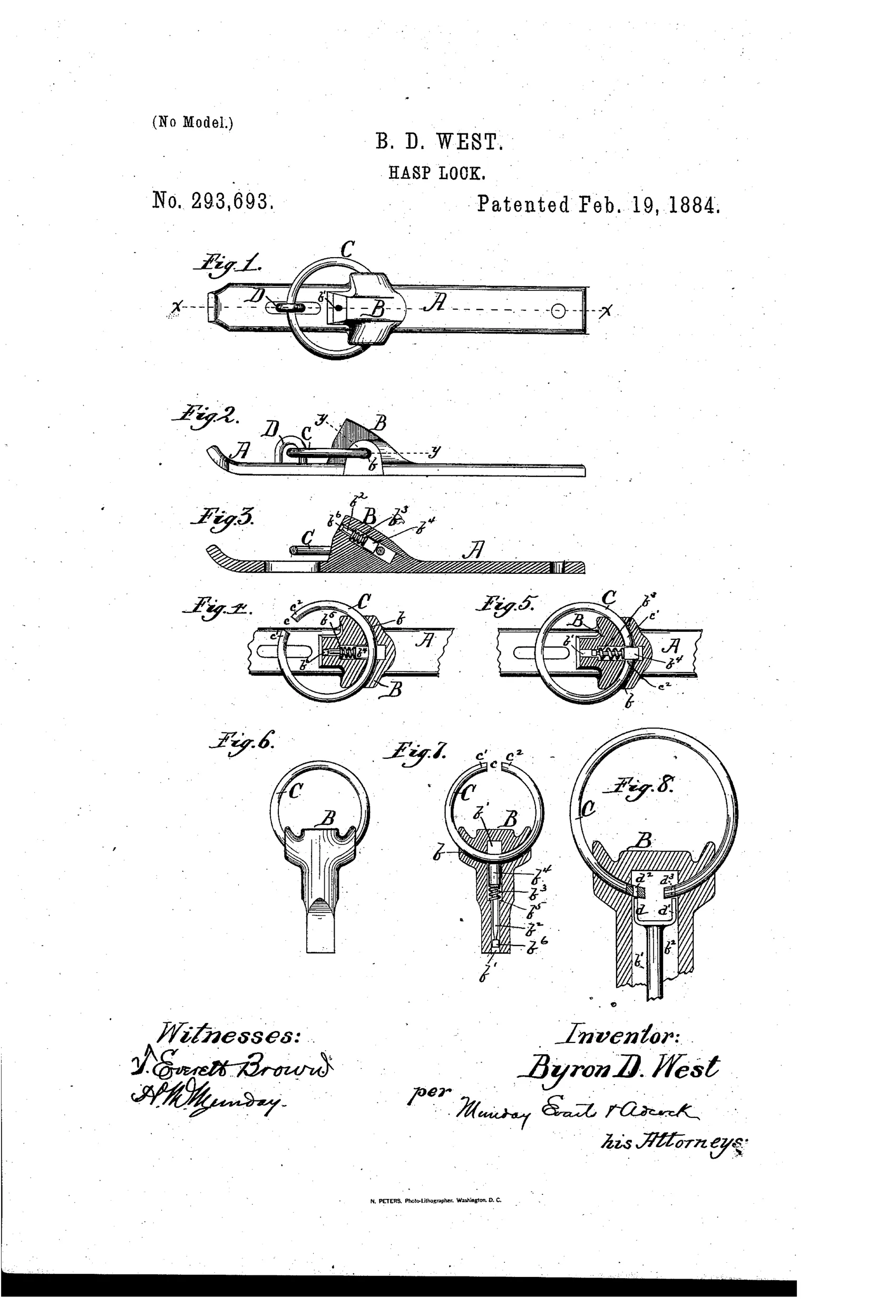
A locking hasp with a broken ring
⚿ How it works
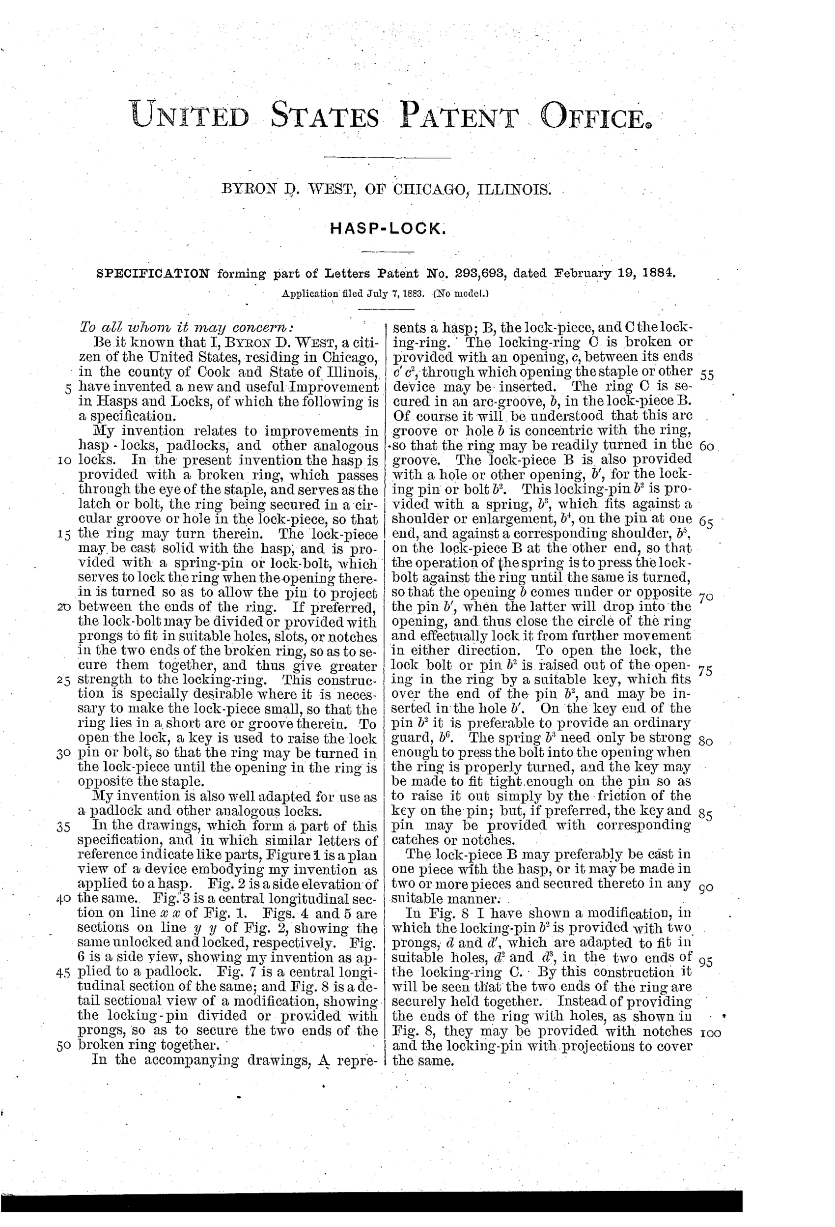
A hasp A carries a rigidly attached lock-piece B holding a broken locking-ring C in a concentric arc-groove, the ring passing through a staple eye D to act as latch. The lock-piece contains a spring-loaded locking-pin b2 that presses against the ring until its opening aligns with the pin, at which point the pin drops in and closes the ring's circle, preventing further rotation. A key inserted over the pin end raises the bolt out of the ring's opening to unlock, allowing the ring to turn until its opening again clears the staple. A modification uses a two-pronged locking-pin fitting into holes in both ends of the broken ring to clasp them together more securely when locked.
⚿ What was claimed
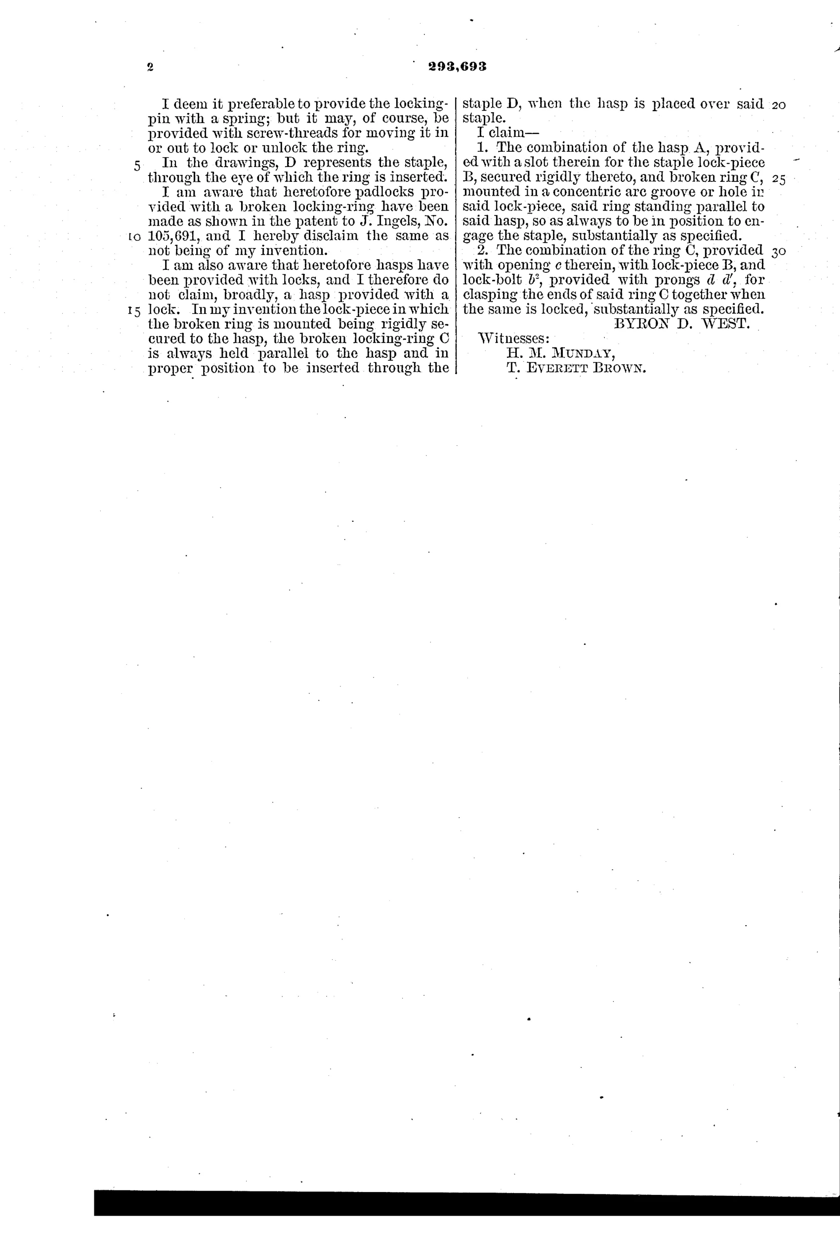
“The combination of the hasp A, provided with a slot therein for the staple lock-piece B, secured rigidly thereto, and broken ring C, mounted in a concentric arc groove or hole in said lock-piece, said ring standing parallel to said hasp, so as always to be in position to engage the staple, substantially as specified.”
In plain English: A hasp with a rigidly attached lock-piece holding a broken ring in a curved groove so the ring stays aligned to always catch the staple.
⚿ In the inventor’s words
“I am also aware that heretofore hasps have been provided with locks, and I therefore do not claim, broadly, a hasp provided with a lock.”— Byron D. West, from the specification
Paper patent — likely never produced
No known manufactured hasp-lock or padlock matches this rotating broken-ring design, and its single-pin security offered little to attract a maker; a marked specimen would change the call.
⚿ Commentary
Most padlocks of 1884 work the same way at the top: a shackle heel lifts or pivots clear of the case. West throws that out. His shackle is a broken ring — a circle with a gap — riding in a concentric groove inside the lock-piece, so it never leaves the body at all. To open, you rotate the ring until the gap sweeps past the staple; to lock, you keep turning until a spring-loaded pin drops into the gap, and now the pin itself completes the circle. The bolt doesn't just block the shackle, it becomes the missing arc of it. That's a genuinely tidy inversion, and Figs. 4 and 5 show it well: the same section line, unlocked and locked, with the pin either riding the ring's surface or seated in its break.
The modification in Fig. 8 is the better engineering: a two-pronged pin that enters holes bored in both ends of the broken ring, clasping the two ends together rather than merely filling the gap. That resists someone prying the ring ends apart — the obvious attack on the plain version.
West is candid in the specification that hasp-locks aren't new; he claims only this ring-in-groove arrangement. The weakness is security: the key merely lifts one pin, so this is trunk-and-shed hardware, not a rival to lever or pin-tumbler work. A pleasant mechanical detour rather than a step on the main road.
Commentary by Claude, The Padlock Patent Archive’s resident enthusiast