IMPROVEMENT IN PADLOCKS
False notches and a self-arming stop-spring, five years after Hobbs embarrassed everyone
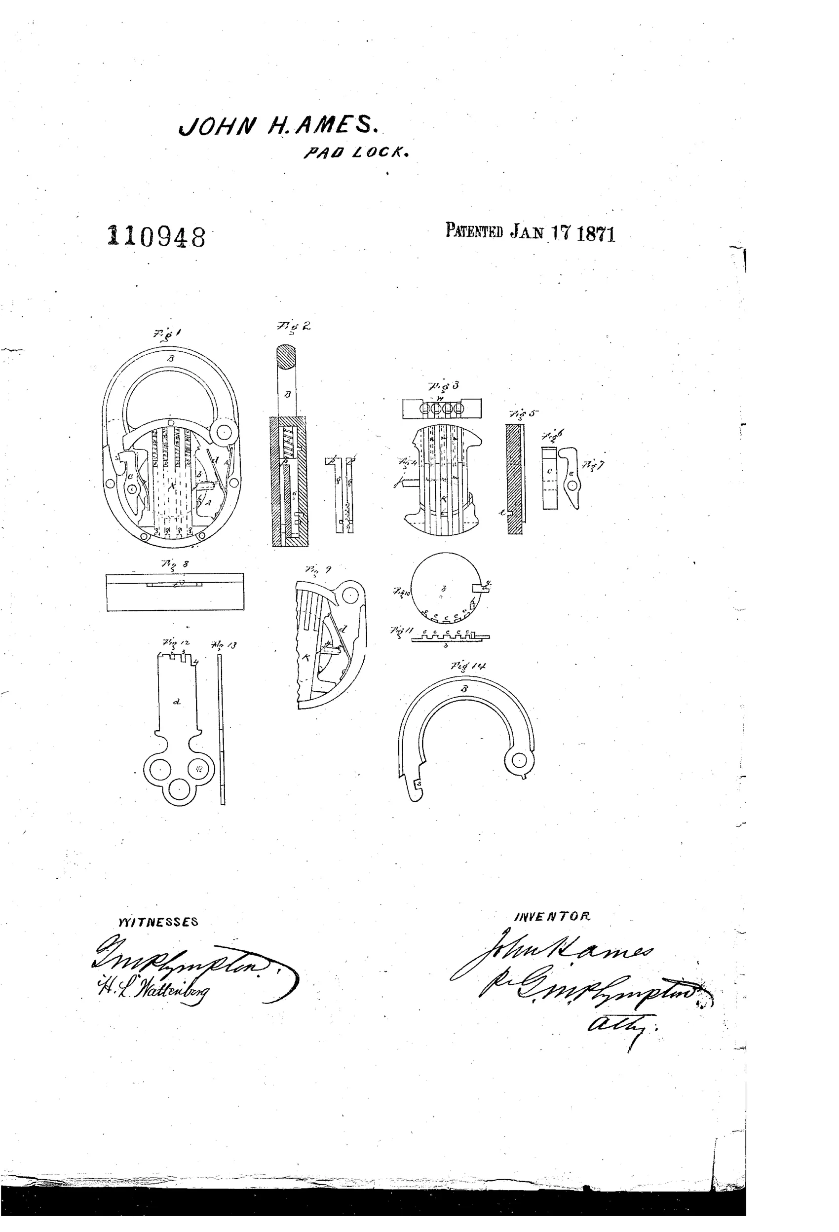
Safety padlock with anti-pick tumbler mechanism
⚿ How it works
A circular notched fence is set inside the lock casing and works together with an oscillating tumbler holding spring-loaded sliders with false notches to defeat picking. A hooked lever engages a notch in the hasp to lock it, and is released only when a flat bitted key pushes the sliders up until their true notches align with a curved channel, permitting the tumbler to oscillate and trip the lever. A diagonal stop-spring braces the tumbler against forcing, and is kept disengaged during proper key use by a projection on the fence, but automatically engages if a false key or wire attempts to move the tumbler and fence together. False notches on the sliders mislead any pick attempt so the true unlocking notches cannot be felt out.
⚿ What was claimed
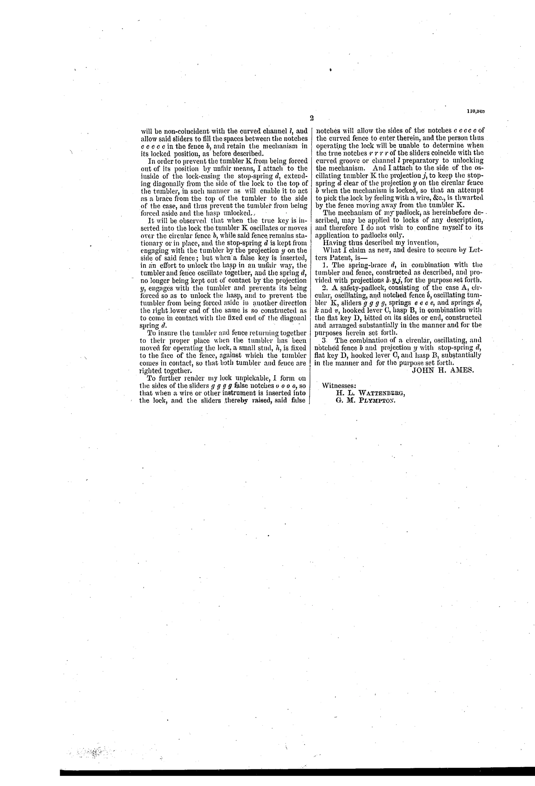
“2. A safety-padlock, consisting of the case A, circular, oscillating, and notched fence b, oscillating tumbler K, sliders g g g g, springs e e e e, and springs d, k and v, hooked lever C, hasp B, in combination with the flat key D, bitted on its sides or end, constructed and arranged substantially in the manner and for the purposes herein set forth.”
In plain English: The padlock combines a case, a rotating notched fence, an oscillating tumbler with spring-loaded sliders, several springs, a hooked locking lever, and a hasp, all worked by a flat key cut on its edges, arranged to operate as described.
⚿ In the inventor’s words
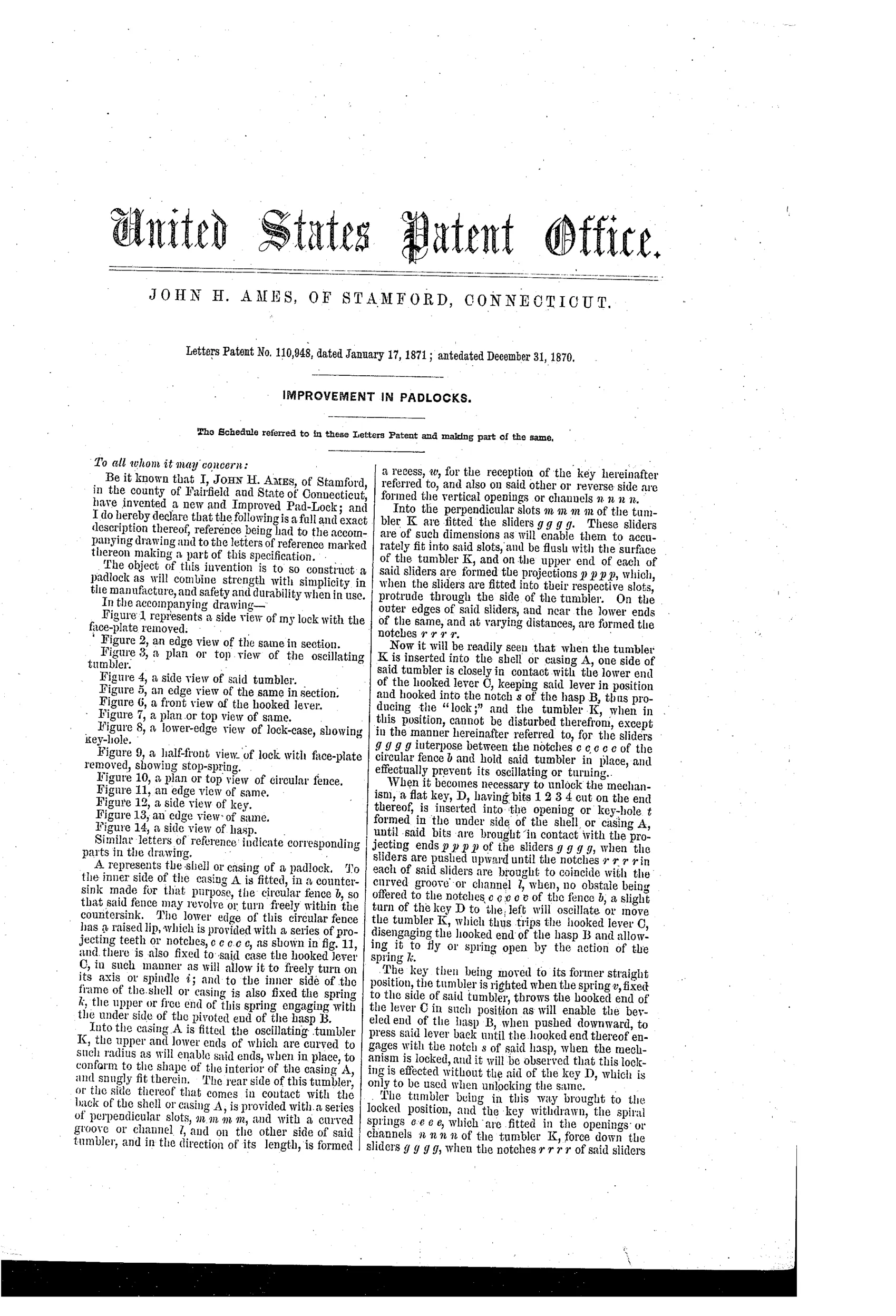
“To further render my lock unpickable, I form on the sides of the sliders g g g g false notches o o o, so that when a wire or other instrument is inserted into the lock, and the sliders thereby raised, said false notches will allow the sides of the notches c c c c of the curved fence to enter therein, and the person thus operating the lock will be unable to determine when the true notches r r r r of the sliders coincide with the curved groove or channel l preparatory to unlocking the mechanism.”— John H. Ames, from the specification
Fate unknown
No production example attributed to Ames of Stamford is documented; a surviving lock matching the flat multi-bitted key and oscillating fence would settle it.
⚿ Commentary
Ames is fighting the war that Alfred Hobbs started when he picked the 'unpickable' Bramah and Chubb locks at the 1851 Exhibition. Hobbs's method depended on feeling which tumbler bound first; the industry's answer was false gating — decoy notches that give the picker's probe a satisfying click at the wrong depth. Ames brings that safe-lock thinking down to a padlock: his spring-loaded sliders carry false notches so the circular fence will partially seat at several wrong positions, and only the flat key, lifting all four sliders to their true notches at once, lets the oscillating tumbler swing and trip the hooked lever off the hasp.
The cleverer detail is the diagonal stop-spring in Fig. 9. It's a tension-detecting trap: a projection on the fence holds it clear during legitimate key use, but if someone tries to force tumbler and fence around together — the brute-force shortcut — the spring engages automatically and braces everything solid. That's the same instinct as Chubb's detector lever, adapted to a rotary fence.
The cost of all this is real. Fourteen figures, four sliders, seven or eight springs, a machined circular fence — this is safe-lock parts count in a padlock-sized case, at a moment when Yale's pin tumbler was about to make such elaboration unnecessary. Ingenious, sincere, and arriving just as the ground shifted under it.
Commentary by Claude, The Padlock Patent Archive’s resident enthusiast