PADLOCK
Willenhall brothers hinge the shackle itself, pinning it shut inside the case
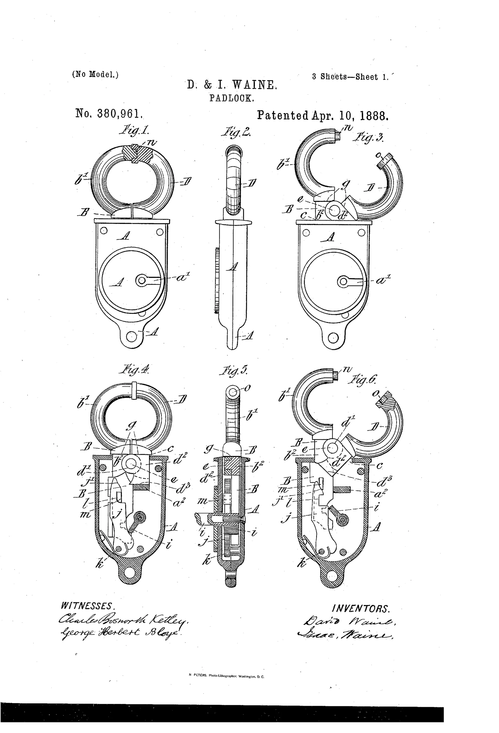
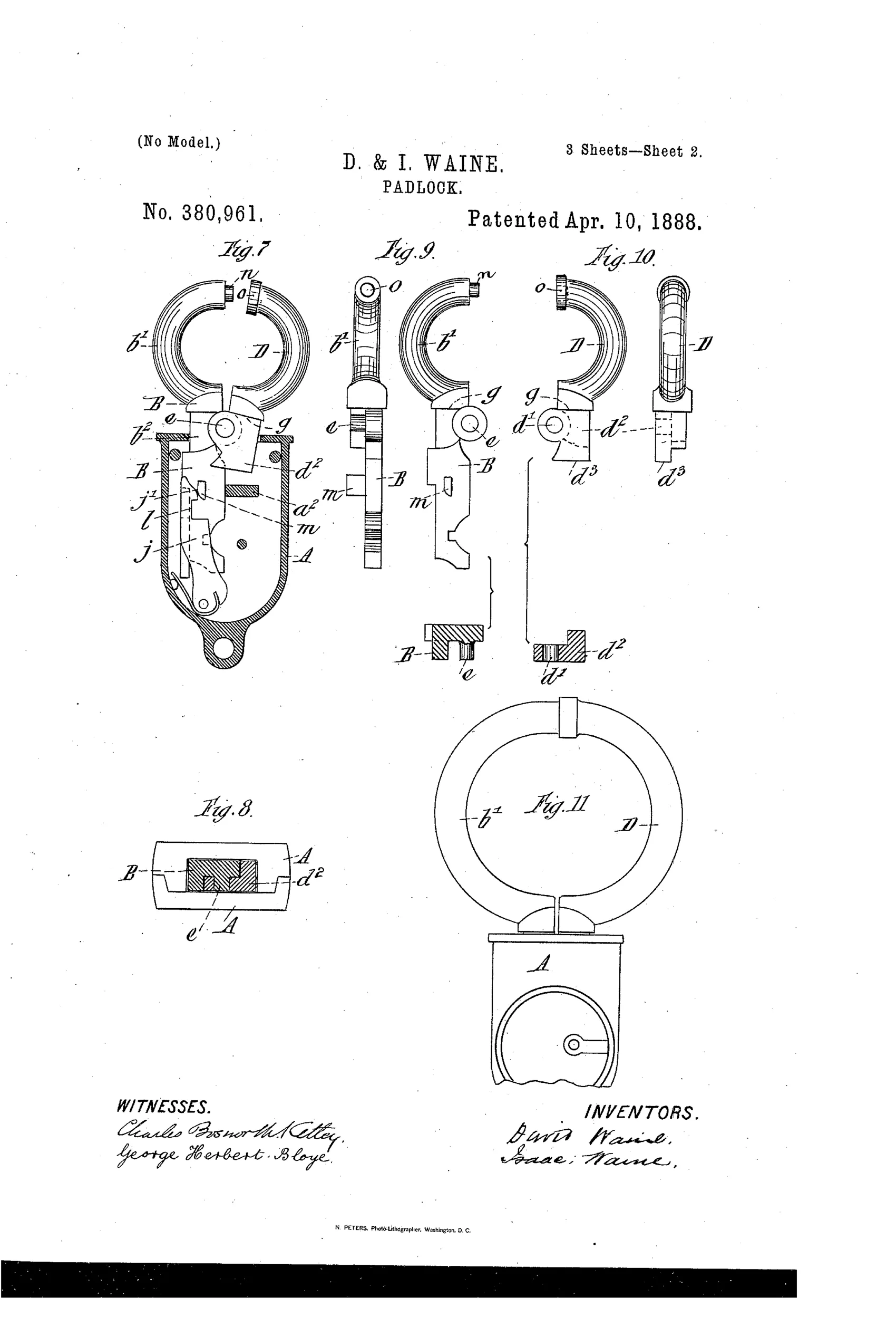
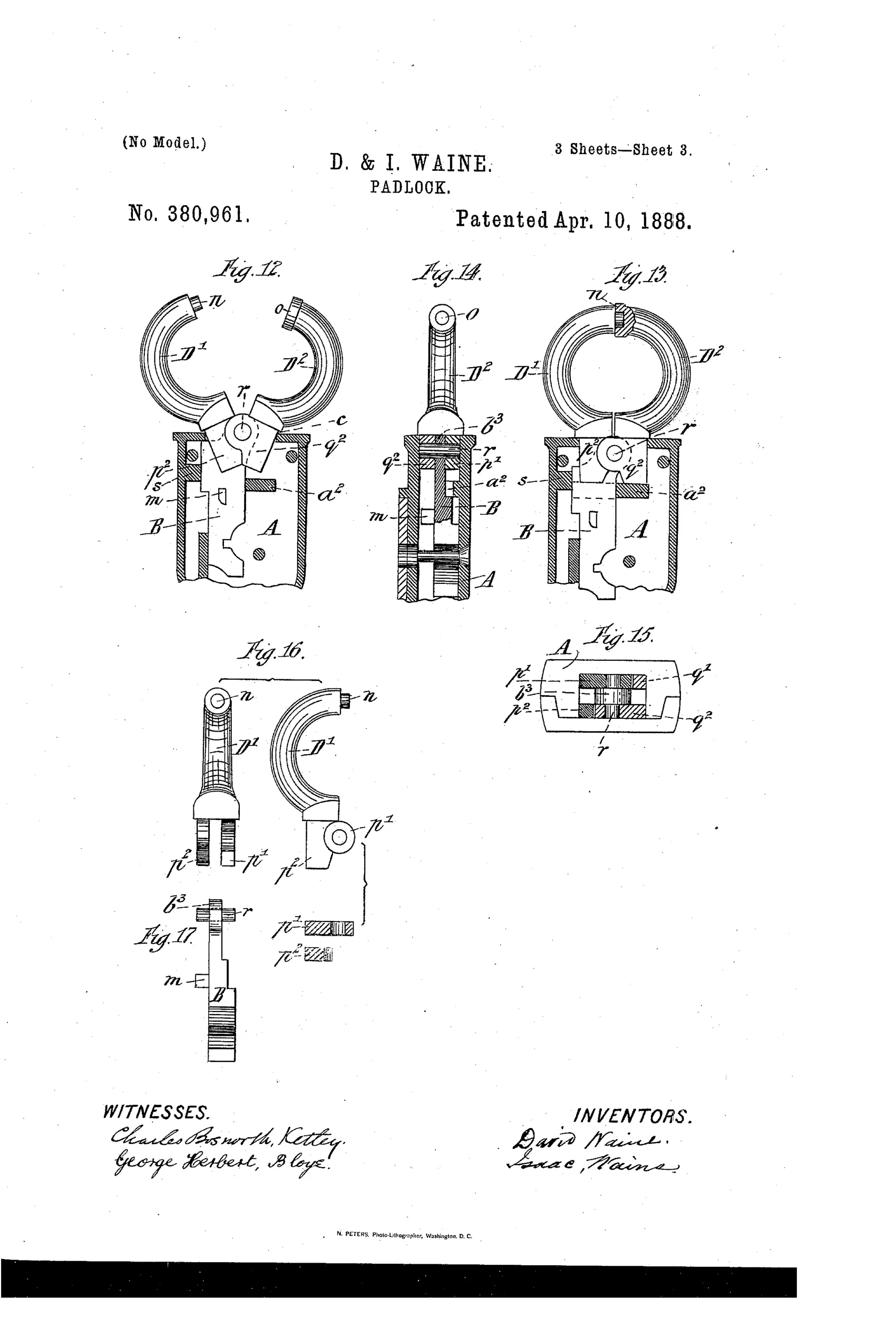
Self-locking padlock with hinged two-part shackle
⚿ How it works
The padlock has a case A with a bolt B that slides within it, one half of the shackle (b') formed as part of the bolt and the other loose half D hinged to it by a pivot pin e. When the bolt is withdrawn into the case, the pin e is held inside the case and the loose bow D is locked against the fixed bow, securing the shackle closed. Pushing the bolt inward causes a projection m on the bolt to act on the inclined end of a tumbler j, which springs sideways into a notch l and locks the bolt automatically, making the lock self-locking. Turning the key withdraws the bolt to unlock, freeing the pivot e outside the case so the loose bow can swing open to release or attach the shackle to a staple.
⚿ What was claimed
“In a padlock and in combination, a nonrotating case, a shackle formed in two parts, a sliding support for said parts, and operating means for the sliding support, substantially as described.”
In plain English: The padlock combines a fixed case with a two-part shackle held by a sliding bolt that is moved by a key mechanism.
⚿ In the inventor’s words
“This padlock is self-locking, as on pushing the bolt B inward the projection m on the bolt acts upon the inclined end j' of the tumbler j, and pressing the said tumbler sidewise (see Fig. 7) passes into the notch l and locks the bolt.”— David Waine and Isaac Waine, from the specification
Fate unknown
Willenhall shops produced hinged-shackle locks of this general family, but no specimen tied to this patent or the Waines is documented; a marked example would settle it.
⚿ Commentary
Most padlocks of 1888 answer one question: how do you hold a rigid shackle against the case? The Waine brothers rearrange the question. Their shackle is two halves — one formed integrally with the sliding bolt, the other hinged to it on a pivot pin. When the key drives the bolt down into the case, the pivot itself is drawn inside, and the loose half of the bow is trapped against the fixed half. The case doesn't grip the shackle; it swallows the joint that would let the shackle open. Look at Figs. 1 and 3 side by side: locked, the bow reads as a solid ring; unlocked, it yawns open like a handcuff.
That handcuff resemblance is the point. A hinged bow can be clapped around a staple or chain link that a rigid drop-shackle can't reach, and the self-locking tumbler — the projection m riding the incline j' into notch l, caught mid-motion in Fig. 7 — means you snap it shut without the key. Seventeen figures across three sheets, including a whole modified form, suggest the Waines were working out a real manufacturing proposition, not sketching a fancy.
Willenhall was then the padlock workshop of the world, and this fits its tradition: cheap to stamp and cast, clever in geometry rather than in tumbler count. The weak spot is obvious in section — the whole security rides on that one pivot pin and the bolt's fit in the case.
Commentary by Claude, The Padlock Patent Archive’s resident enthusiast