TRICK-LOCK
A padlock that stabs you for turning your own key
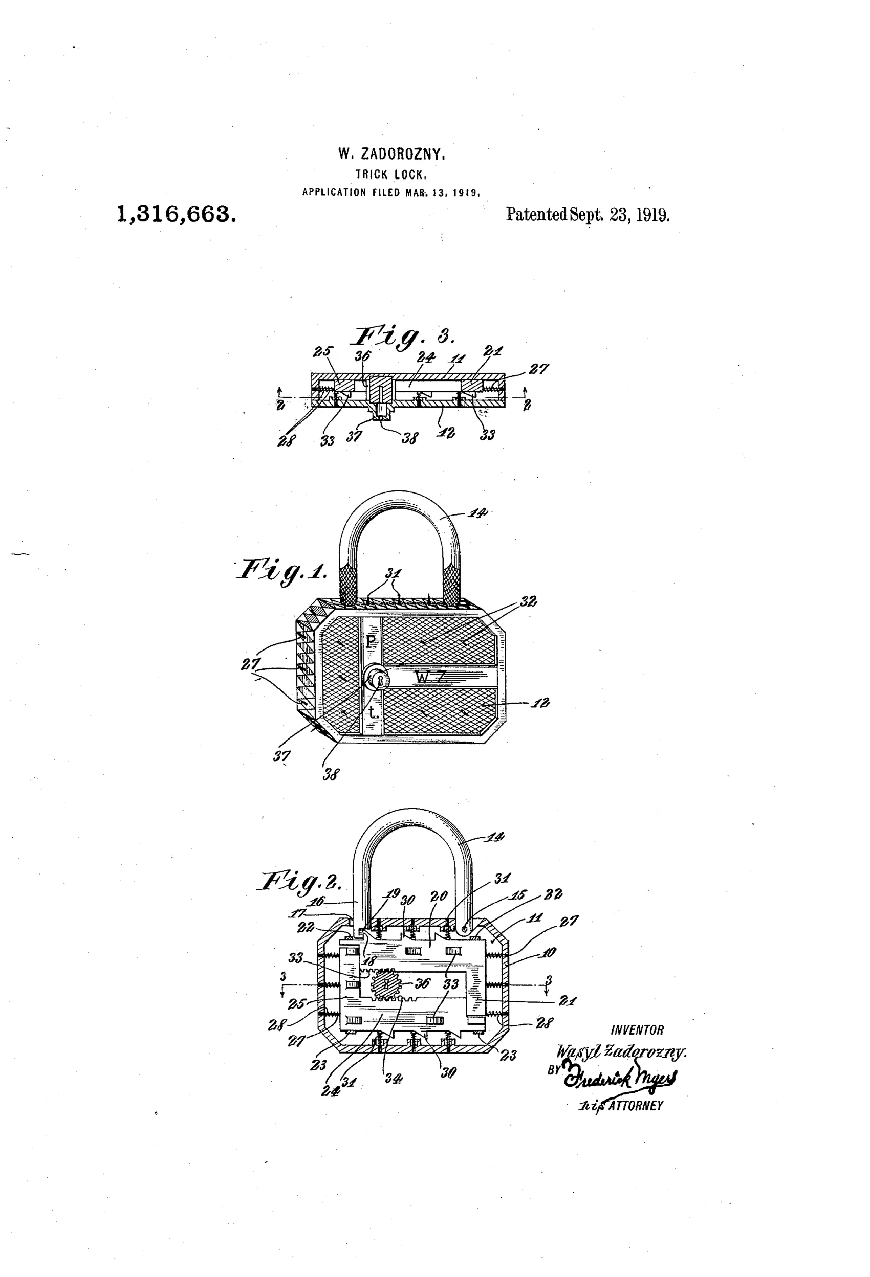
Padlock with hidden needle-pin defense mechanism
⚿ How it works
The padlock body houses a pair of slidable longitudinal bars whose adjacent inner edges carry rack teeth meshing with a central pinion turned by the key. Turning the key drives the bars outward, which compresses coiled springs and forces sharply pointed pins outward through openings in the casing walls, top, and cover. The same outward bar motion also disengages a detent from a recess in the U-shaped shackle, releasing the lock, but only after the pins have already projected. Anyone unfamiliar with the correct grip is thus likely to be pierced by the needle-like pins when attempting to operate the lock.
⚿ What was claimed
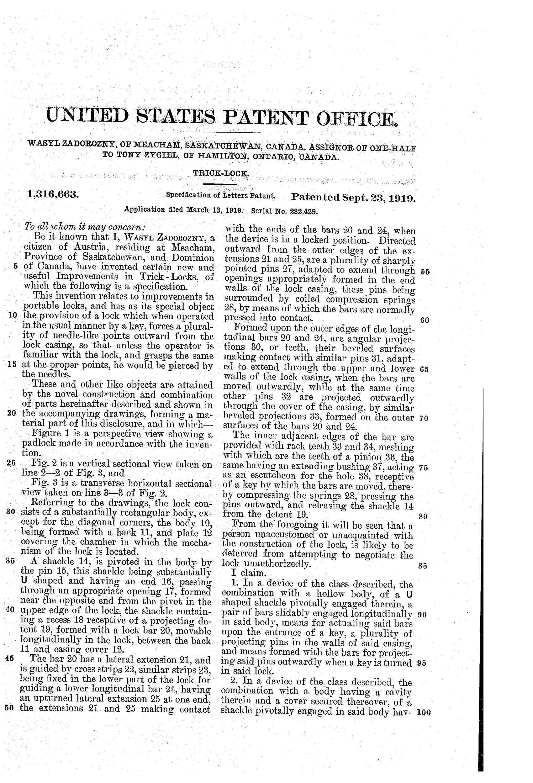
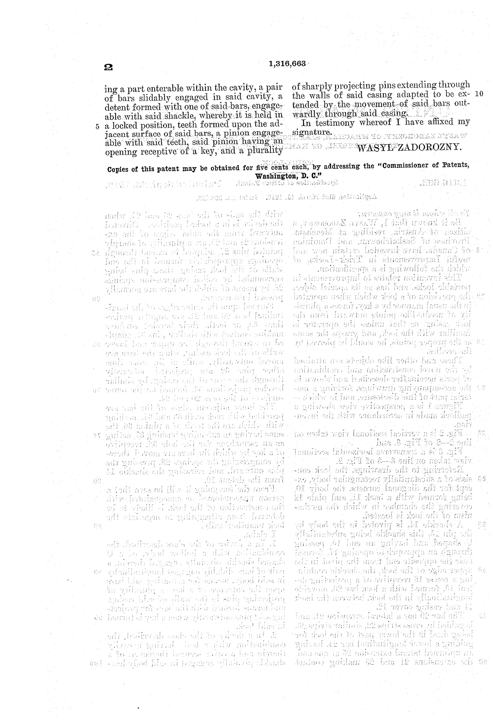
“In a device of the class described, the combination with a hollow body, of a U shaped shackle pivotally engaged therein, a pair of bars slidably engaged longitudinally in said body, means for actuating said bars upon the entrance of a key, a plurality of projecting pins in the walls of said casing, and means formed with the bars for projecting said pins outwardly when a key is turned in said lock.”
In plain English: The lock combines a pivoted U-shaped shackle in a hollow body with a pair of key-actuated sliding bars that push sharp pins outward through the casing walls whenever the key is turned.
⚿ In the inventor’s words
“From the foregoing it will be seen that a person unaccustomed or unacquainted with the construction of the lock, is likely to be deterred from attempting to negotiate the lock unauthorizedly.”— Wasyl Zadorozny, from the specification
Paper patent — likely never produced
No production example of a pin-projecting trick padlock is known, and the liability and practicality problems make manufacture implausible.
⚿ Commentary
Most trick locks of this era hide the keyhole, demand a secret twist of the shackle, or require pressing a false rivet. Zadorozny of Meacham, Saskatchewan went another direction entirely: his lock punishes. Turning the key spins a central pinion meshed with two rack-toothed bars; as the bars slide outward they shove needle-sharp pins through openings in the case walls, top, and cover — and only after the pins are out does a detent release the shackle. The 'trick' is knowing where to grip so you aren't perforated by your own padlock.
Fig. 2 rewards a close look. The spring-loaded pins (27, 28) ring nearly the whole case, and the geometry guarantees the pins deploy before the shackle frees. The rack-and-pinion drive is genuinely competent drafting — this isn't a crank's sketch, it's a workable mechanism aimed at a very strange goal.
The fatal problems are obvious with a moment's thought: the legitimate owner faces the pins every single day, the open pin holes invite dirt and ice (this is Saskatchewan), and any thief with gloves or a rag defeats the entire deterrent. As a booby trap it also flirts with legal trouble that no manufacturer would touch. It sits in the trick-lock tradition as an amusing dead end — the puzzle lock's belligerent cousin, patented in earnest and, so far as I can tell, never inflicted on the public.
Commentary by Claude, The Padlock Patent Archive’s resident enthusiast