PADLOCK
A false keyhole to fool the burglar, a rotating disk to hide the real one
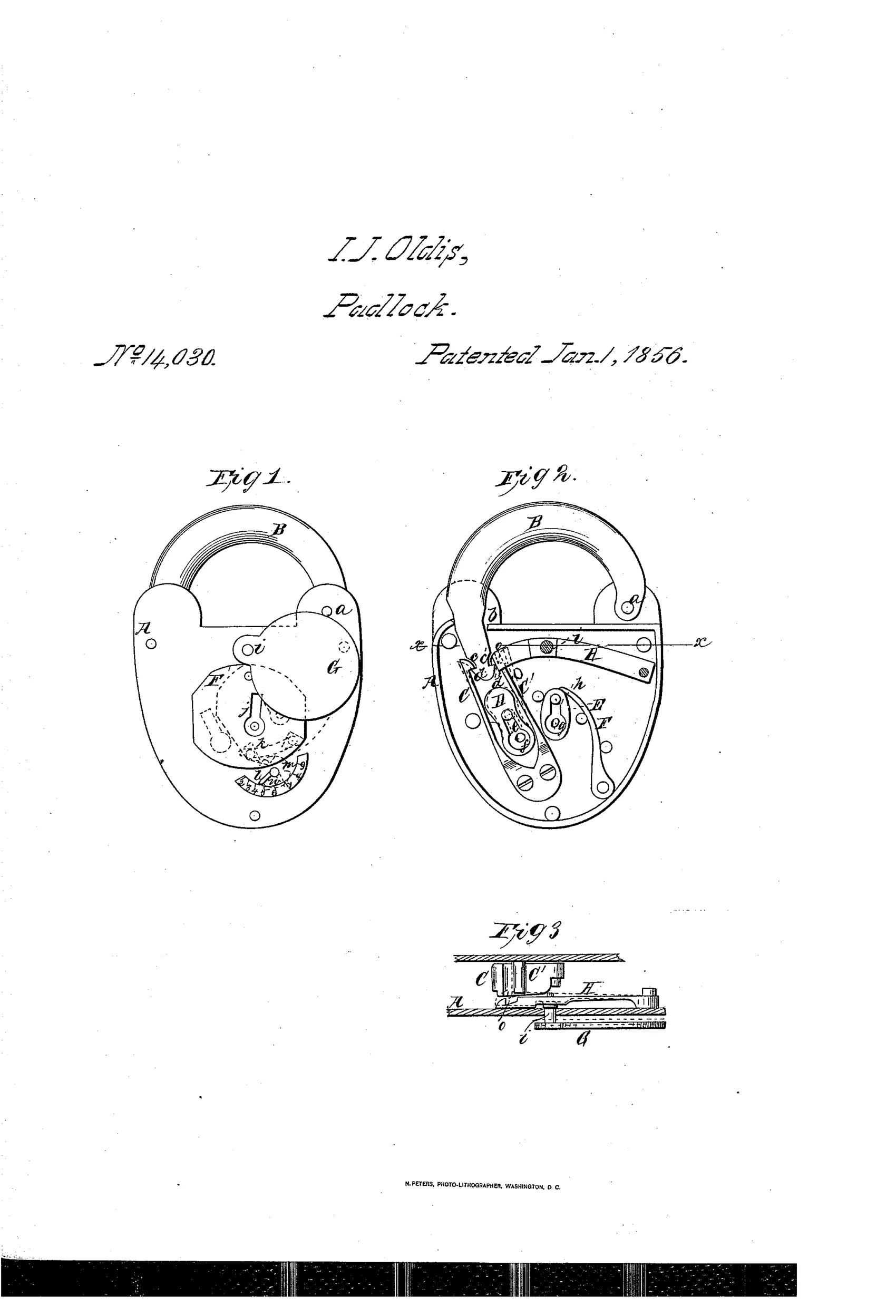
Padlock with concealed, decoy false keyhole
⚿ How it works
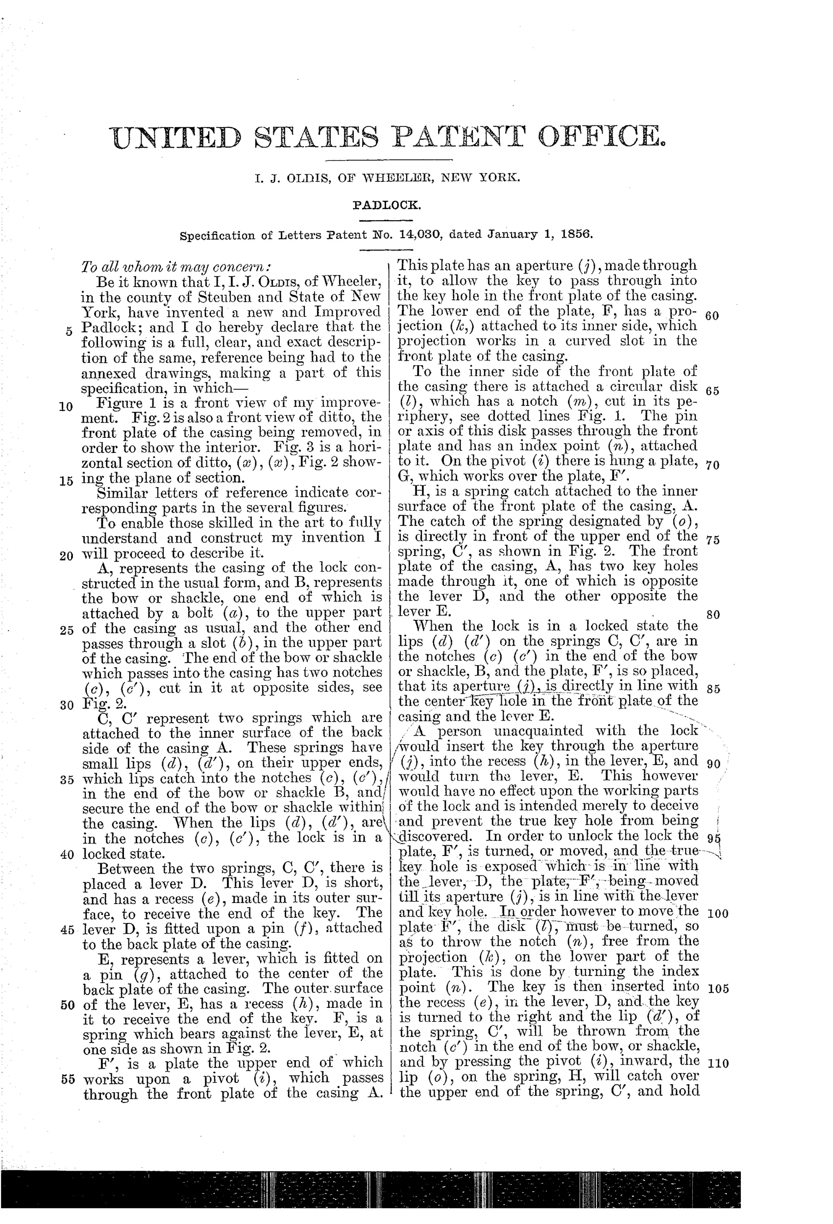
The shackle end has two notches that are caught by lips on two springs mounted inside the casing, locking it in place. A decoy lever with a false keyhole is provided to deceive anyone unfamiliar with the true mechanism, while a rotating disk with a notch and index point must be aligned to free a sliding plate that reveals the true keyhole over the real lever. Turning the key in the true keyhole releases the spring lips from the shackle notches in sequence, and a spring catch (H) holds the mechanism in the unlocked position until the shackle is closed again.
⚿ What was claimed
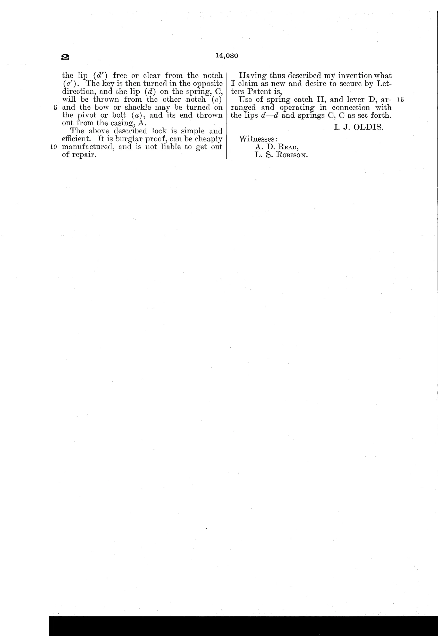
“Use of spring catch H, and lever D, arranged and operating in connection with the lips d—d and springs C, C as set forth.”
In plain English: The invention claims the specific combination of a spring catch and lever working together with the spring lips to hold and release the shackle.
⚿ In the inventor’s words
“The above described lock is simple and efficient. It is burglar proof, can be cheaply manufactured, and is not liable to get out of repair.”— I. J. Oldis, from the specification
Fate unknown
No production example of this decoy-keyhole design is documented; a surviving specimen matching the Fig. 1 case would settle it, though small-town trick locks of this era rarely reached manufacture.
⚿ Commentary
Oldis of Wheeler, New York, is playing a security game that was very much alive in 1856: don't out-engineer the picker, deceive him. The lock has a fully formed decoy keyhole sitting over a dummy lever — a picklock could work at it all day and accomplish nothing. The real keyhole hides behind a sliding plate that only moves once a rotating disk is turned so its notch lines up with an index point. It's a trick lock with a permutation-style gatekeeper bolted onto a conventional spring-shackle mechanism.
The honest engineering is in Fig. 2. The shackle heel carries two notches caught by lips on a pair of internal springs — a doubled version of the plain spring catch found in cheap locks of the day. The key releases the lips in sequence, and the spring catch H is a genuinely thoughtful touch: it holds everything in the released position so the key can come out and the shackle re-engages cleanly when snapped shut. That claim, not the decoy, is what the Patent Office actually granted.
The weakness is the one that haunts all secrecy-based locks: the disk-and-index alignment is a secret, not a combination. Anyone who has seen one lock of this pattern knows the trick forever. Yale's pin tumbler, still a few years off, would win precisely because it didn't depend on the user's discretion. This is a charming late entry in the deception school, four years before that school closed.
Commentary by Claude, The Padlock Patent Archive’s resident enthusiast