PADLOCK.
Crossed tumblers and a twisted key bolt both shackle legs at once
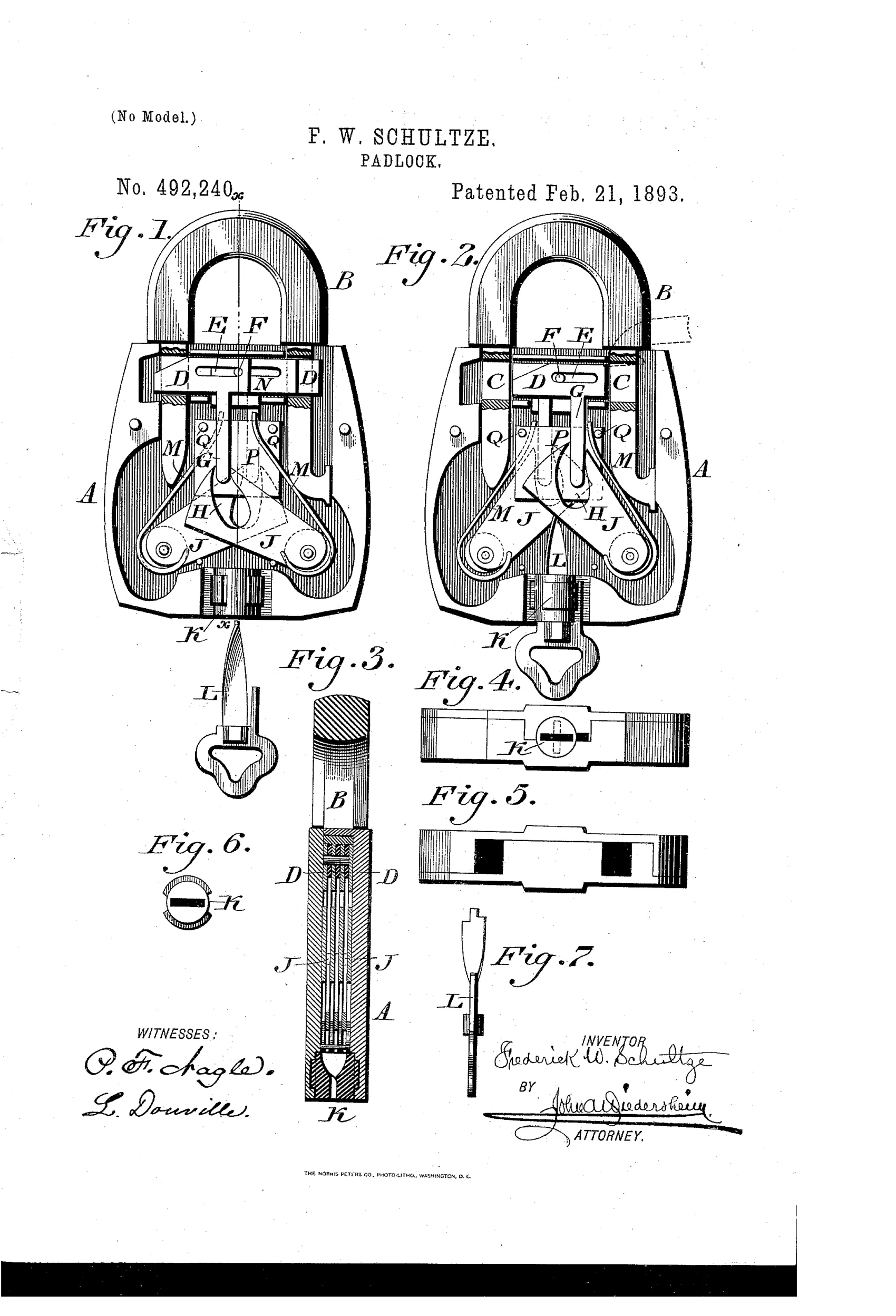
Padlock with sliding dogs engaging shackle openings
⚿ How it works
A shackle B has openings C in its limbs that are engaged by sliding dogs D. The dogs have stems G that ride in curved slots H of pivoted tumblers J, so that the tumblers' opposite curvature drives the dogs in opposite directions. Springs M bias the tumblers to hold the dogs either engaged in the shackle openings (locked) or withdrawn (unlocked). A spiral or twisted key L, rotatably mounted in a bushing K, engages the underside of the tumblers at their point of crossing and forces them apart to release the shackle.
⚿ What was claimed
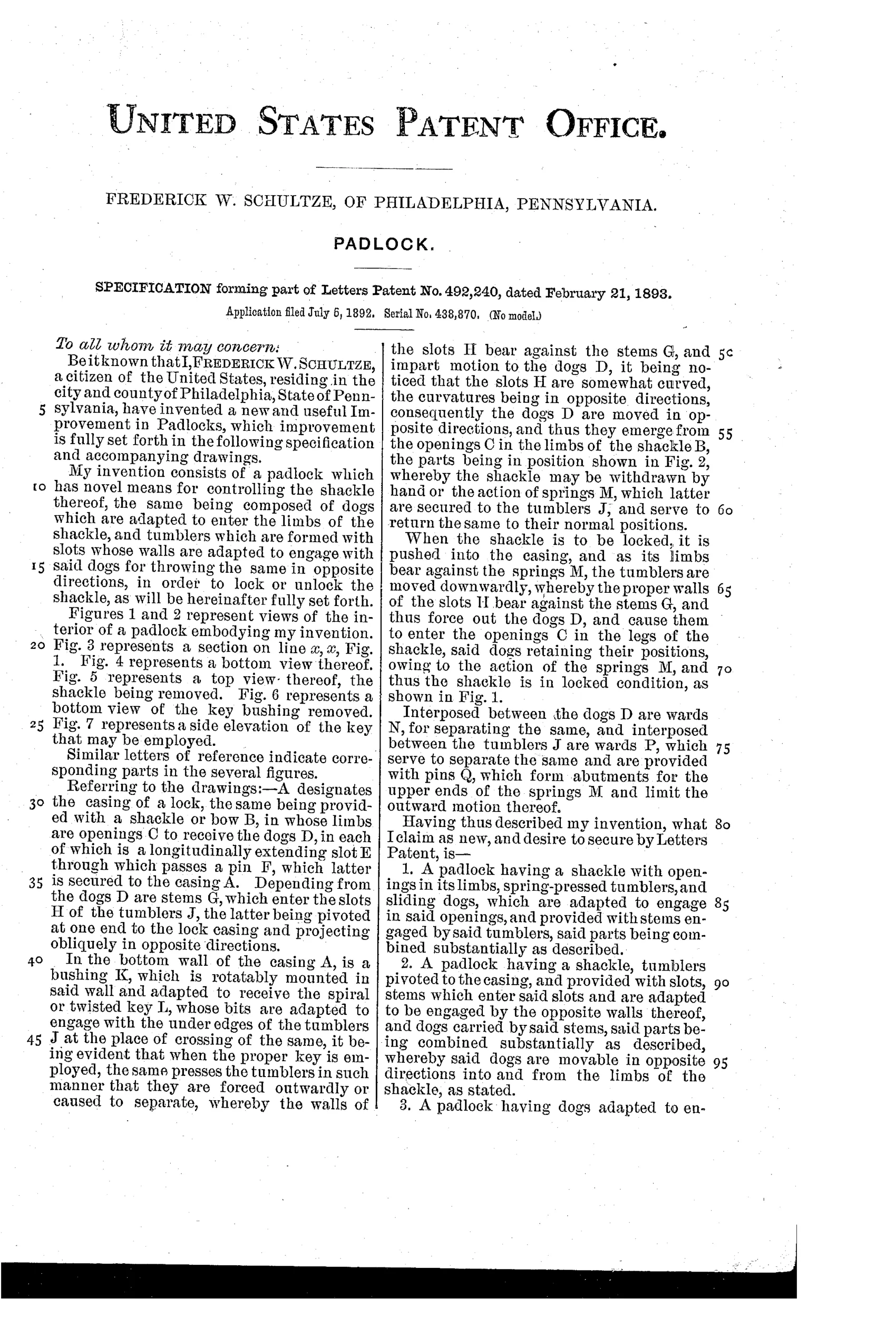
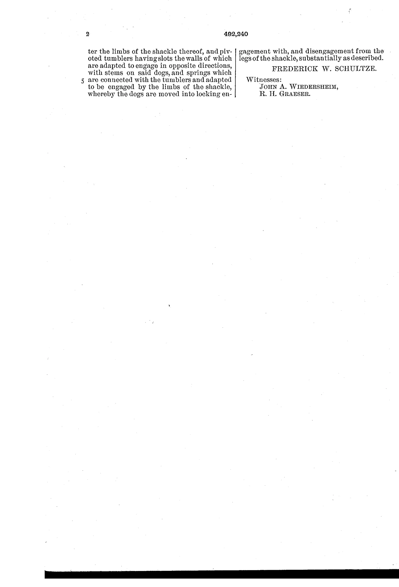
“A padlock having a shackle with openings in its limbs, spring-pressed tumblers, and sliding dogs, which are adapted to engage in said openings, and provided with stems engaged by said tumblers, said parts being combined substantially as described.”
In plain English: A padlock whose shackle has openings engaged by spring-loaded dogs that are moved by tumblers via stems on the dogs.
⚿ In the inventor’s words
“My invention consists of a padlock which has novel means for controlling the shackle thereof, the same being composed of dogs which are adapted to enter the limbs of the shackle, and tumblers which are formed with slots whose walls are adapted to engage with said dogs for throwing the same in opposite directions, in order to lock or unlock the shackle, as will be hereinafter fully set forth.”— Frederick W. Schultze, from the specification
Fate unknown
No production lock matching this crossed-tumbler, spiral-key design is documented; a surviving specimen or maker's catalog entry would settle it.
⚿ Commentary
Most padlocks of 1893 held the shackle at one point — a toe notch, maybe a heel pivot. Schultze bolts both limbs simultaneously. His two dogs D slide horizontally into openings cut through each shackle leg, and the clever part is how they move: each dog carries a stem riding in a curved slot of a pivoted tumbler, and the two tumblers cross like scissor blades with opposite curvature. Swing the tumblers apart and the geometry drives the dogs in opposite directions, out of the shackle. Springs snap everything back when the shackle is reinserted.
The key is the other oddity. It's not turned in a keyhole in the ordinary sense — it's a spiral-twisted blade (Fig. 7) that rotates in a bushing at the bottom of the case and bears against the underside of the tumblers right where they cross. Rotating the key screws the tumblers apart, a bit like a corkscrew pushing a lever. Compare Figs. 1 and 2 and you can watch the whole linkage swing.
As security it's thin — one twisted key shape, no real differing, and the six-lever push-key locks then flooding the market offered far more key changes for similar cost. As mechanism it's charming, a self-contained bit of kinematics. It reads as a dead end: elegant motion in service of a lock that a bent wire at the bushing might defeat.
Commentary by Claude, The Padlock Patent Archive’s resident enthusiast