IMPROVEMENT IN PADLOCKS
A cam-groove spindle does the bolt work in this 1878 tubular oddity
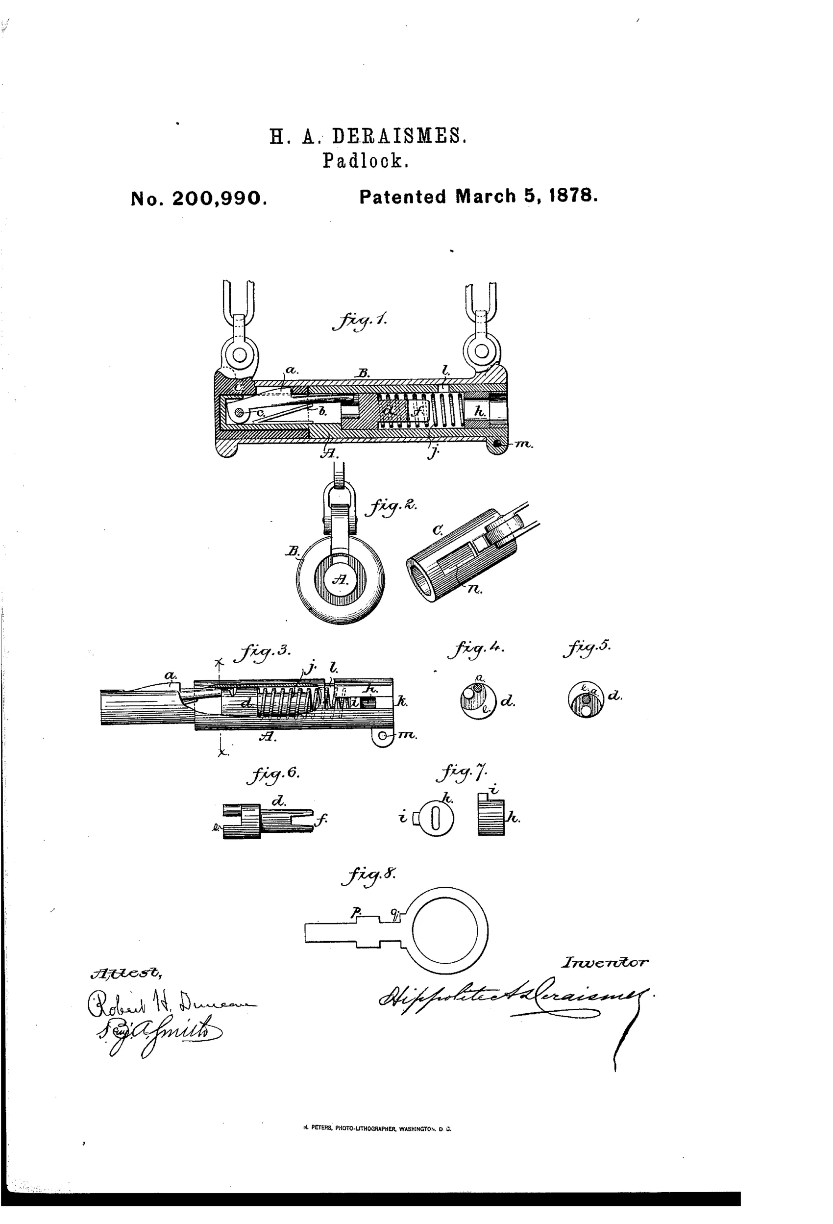
Tubular padlock with rotating cam spindle
⚿ How it works
A bolt or catch is pivoted at one end of a cylindrical holder and is thrown upward by a V-shaped spring, its free end resting in a cam-groove on a rotating spindle. Turning the spindle via a key inserted through a slotted tumbler causes the cam groove to depress the bolt, releasing a hollow fastening-slide that fits over the bolt end. A spring-held tumbler moving in longitudinal and transverse slots aligns the key with the spindle slot before the spindle can turn. The whole assembly is enclosed in a metal case with slotted ends to secure the holder and slide in proper position.
⚿ What was claimed
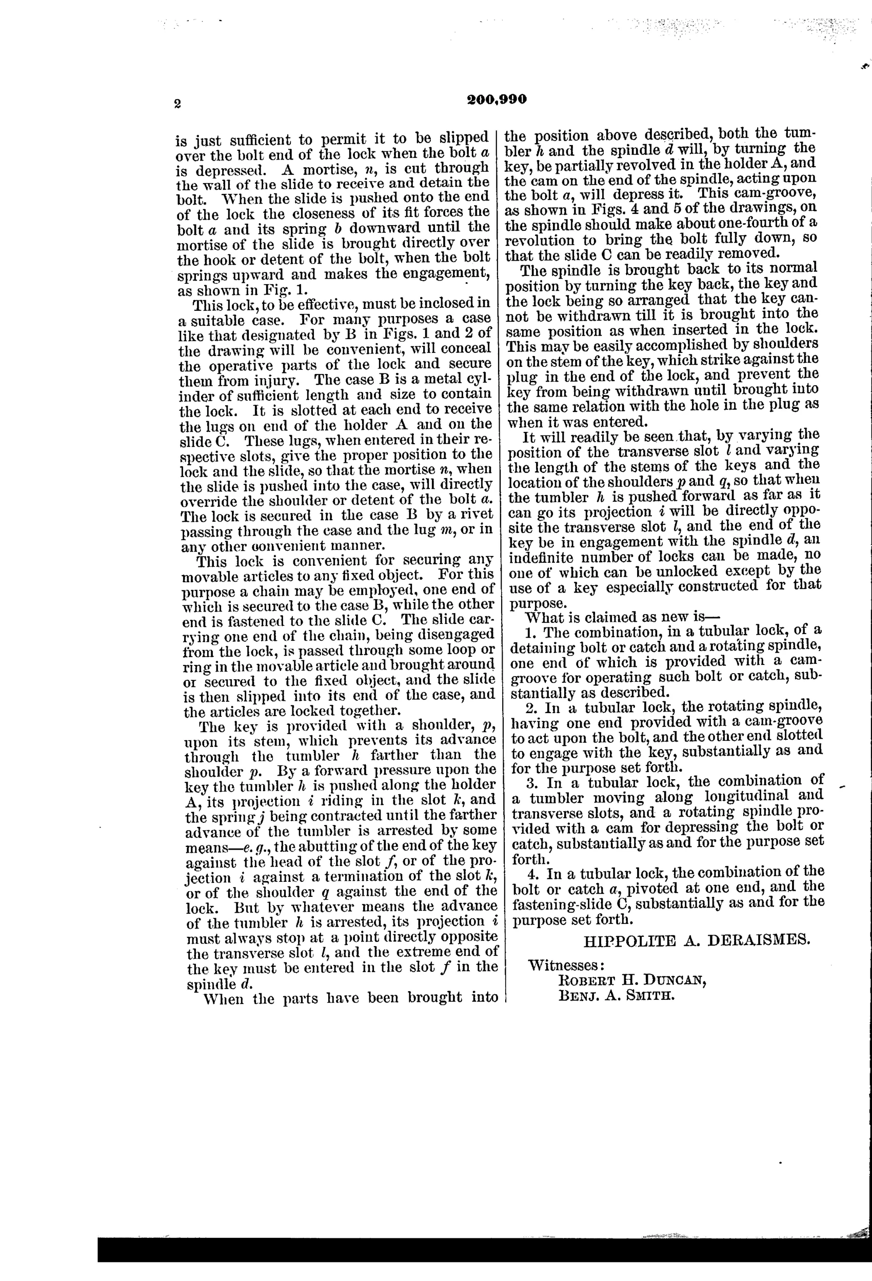
“The combination, in a tubular lock, of a detaining bolt or catch and a rotating spindle, one end of which is provided with a cam-groove for operating such bolt or catch, substantially as described.”
In plain English: A tubular lock where a rotating spindle with a cam groove on its end operates the locking bolt.
⚿ In the inventor’s words
“It will readily be seen that, by varying the position of the transverse slot l and varying the length of the stems of the keys and the location of the shoulders p and q, so that when the tumbler h is pushed forward as far as it can go its projection i will be directly opposite the transverse slot l, and the end of the key be in engagement with the spindle d, an indefinite number of locks can be made, no one of which can be unlocked except by the use of a key especially constructed for that purpose.”— Hippolite A. Deraismes, from the specification
Fate unknown
No production example or maker attribution is documented; a surviving marked specimen of this distinctive two-piece tubular design would settle it.
⚿ Commentary
Deraismes builds his whole lock inside a tube, decades before the word "tubular" meant anything standard in American locks. The bolt pivots at one end of a cylindrical holder, a V-spring throws it up, and its free end rides in a cam groove cut into the end of a rotating spindle. Turn the key, the cam depresses the bolt, and a hollow slide — which is essentially the shackle's working half — pops free. It's the mechanical logic of a latch, rotated ninety degrees and rolled into a cylinder.
The security layer is thinner than the geometry suggests. A single spring-held tumbler slides in longitudinal and transverse slots and must be positioned before the key can engage the spindle slot. Deraismes claims that by shifting the transverse slot and varying key-stem lengths and shoulders, "an indefinite number of locks" can be made. In practice this is one tumbler with dimensional variations — closer to a warded lock's obstacle course than to Yale's pin stack, which by 1878 had already shown what real key differing looked like.
Still, look at Fig. 1 and 2 together: the paired shackle eyes and the withdrawable fastening-slide make this a two-piece lock, closer to a hasp-and-staple fastener than a conventional padlock. That's the interesting dead end here — a self-contained cylindrical closure, elegantly drawn, arriving just as the market was consolidating around cheaper, more familiar forms.
Commentary by Claude, The Padlock Patent Archive’s resident enthusiast