IMPROVEMENT IN PADLOCKS
A shackle you can remove — the trick is a beveled hole and one lug
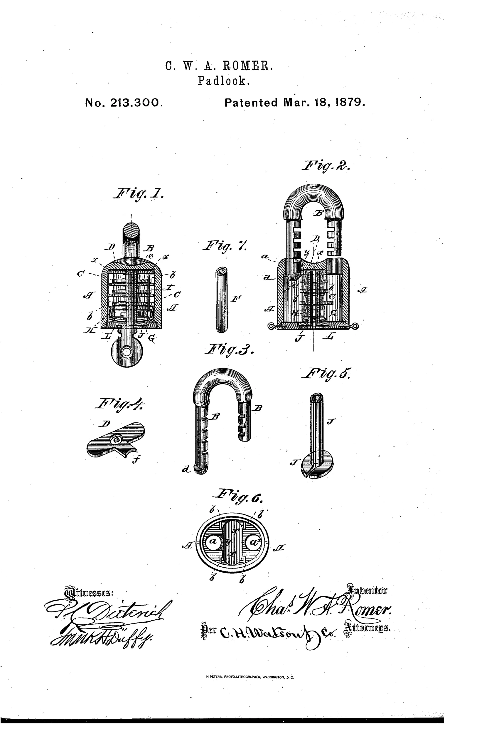
Jail-lock padlock with removable shackle
⚿ How it works
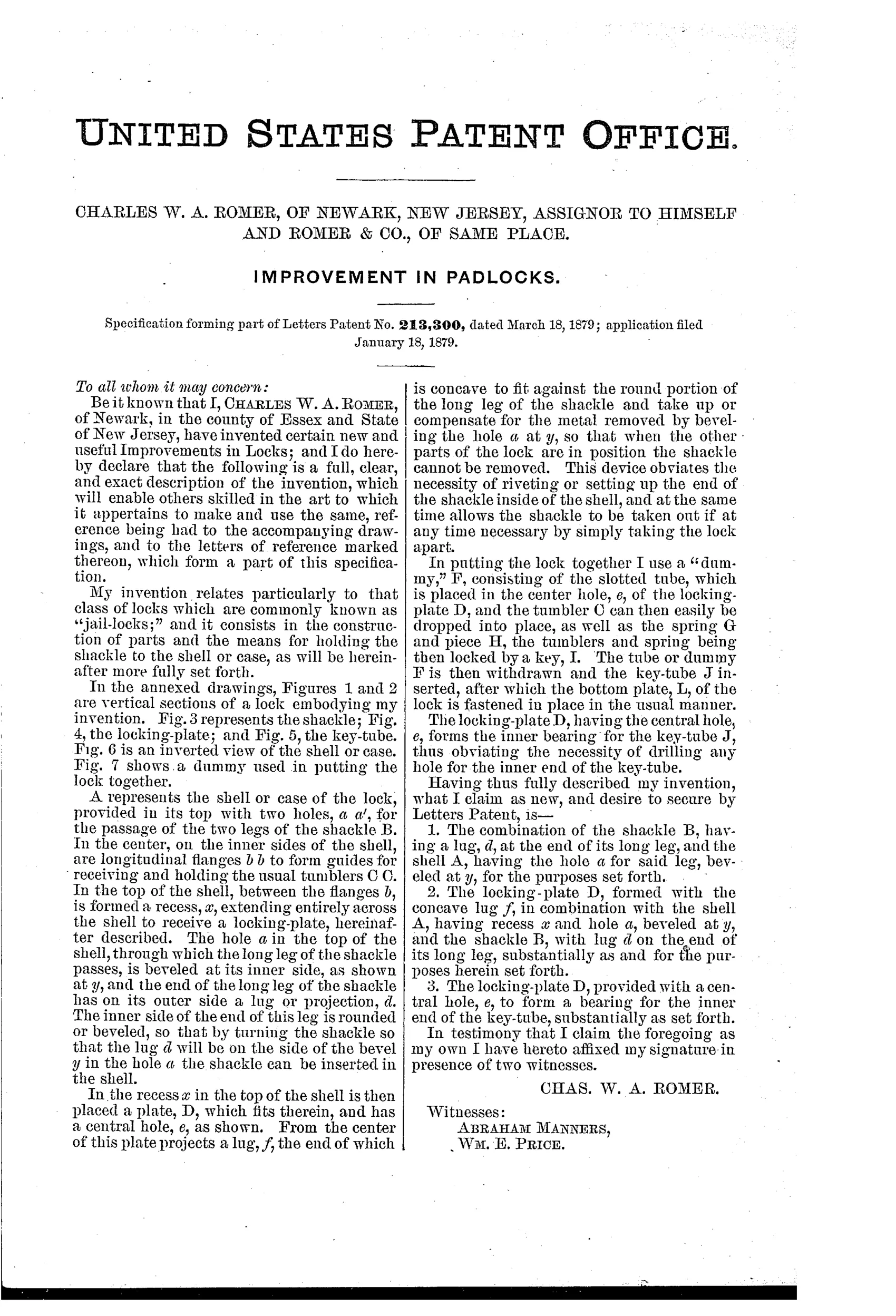
The shackle has a lug at the end of its long leg that fits through a hole in the shell beveled on one side, allowing insertion only when the lug aligns with the bevel. A locking-plate with a central hole and a concave lug seats over the shackle's rounded leg end, compensating for the bevel and preventing removal once assembled. A slotted dummy tube temporarily holds the center hole open so tumblers and springs can be dropped into place before the key-tube is inserted and locked by a key.
⚿ What was claimed
“The combination of the shackle B, having a lug, d, at the end of its long leg, and the shell A, having the hole a for said leg, beveled at y, for the purposes set forth.”
In plain English: A padlock shackle with a lug on its long leg that fits into a beveled hole in the case, allowing insertion only at a specific alignment and locking it in place otherwise.
⚿ In the inventor’s words
“This device obviates the necessity of riveting or setting up the end of the shackle inside of the shell, and at the same time allows the shackle to be taken out if at any time necessary by simply taking the lock apart.”— Charles W. A. Romer, from the specification
Fate unknown
Romer & Co. was a genuine Newark padlock maker, which argues for production, but I know of no documented specimen showing this beveled-lug shackle; disassembling a marked Romer jail lock would settle it.
⚿ Commentary
Most padlock patents of this era chase security. Romer is chasing the assembly line. His problem is mundane and real: the usual way to captivate a shackle was to rivet or peen its long leg inside the shell, which is slow work and makes the lock impossible to service. His answer is a lug on the end of the long leg and a hole in the shell beveled on one side. Rotate the shackle to the one alignment where the lug clears the bevel and it drops in; a locking-plate with a concave lug then seats over the rounded leg end, filling the bevel so the shackle can never find that alignment again — until someone deliberately takes the lock apart.
The part a casual reader will skip is Fig. 7, the slotted dummy tube. It's not a lock component at all; it's a factory fixture that holds the center hole open while the tumblers and springs are dropped into place, after which the real key-tube (Fig. 5) goes in. A patent that draws its own assembly jig is a patent written by someone who actually intended to build the thing.
As a mechanism this is a refinement, not a leap — the lever-tumbler jail lock was well established by 1879. But the assignment to Romer & Co., a working Newark lock house, tells you this was shop knowledge being fenced off, not parlor invention.
Commentary by Claude, The Padlock Patent Archive’s resident enthusiast