IMPROVEMENT IN LOCKS.
A rekeyable pin-tumbler padlock in 1863 — change the pins, change the key
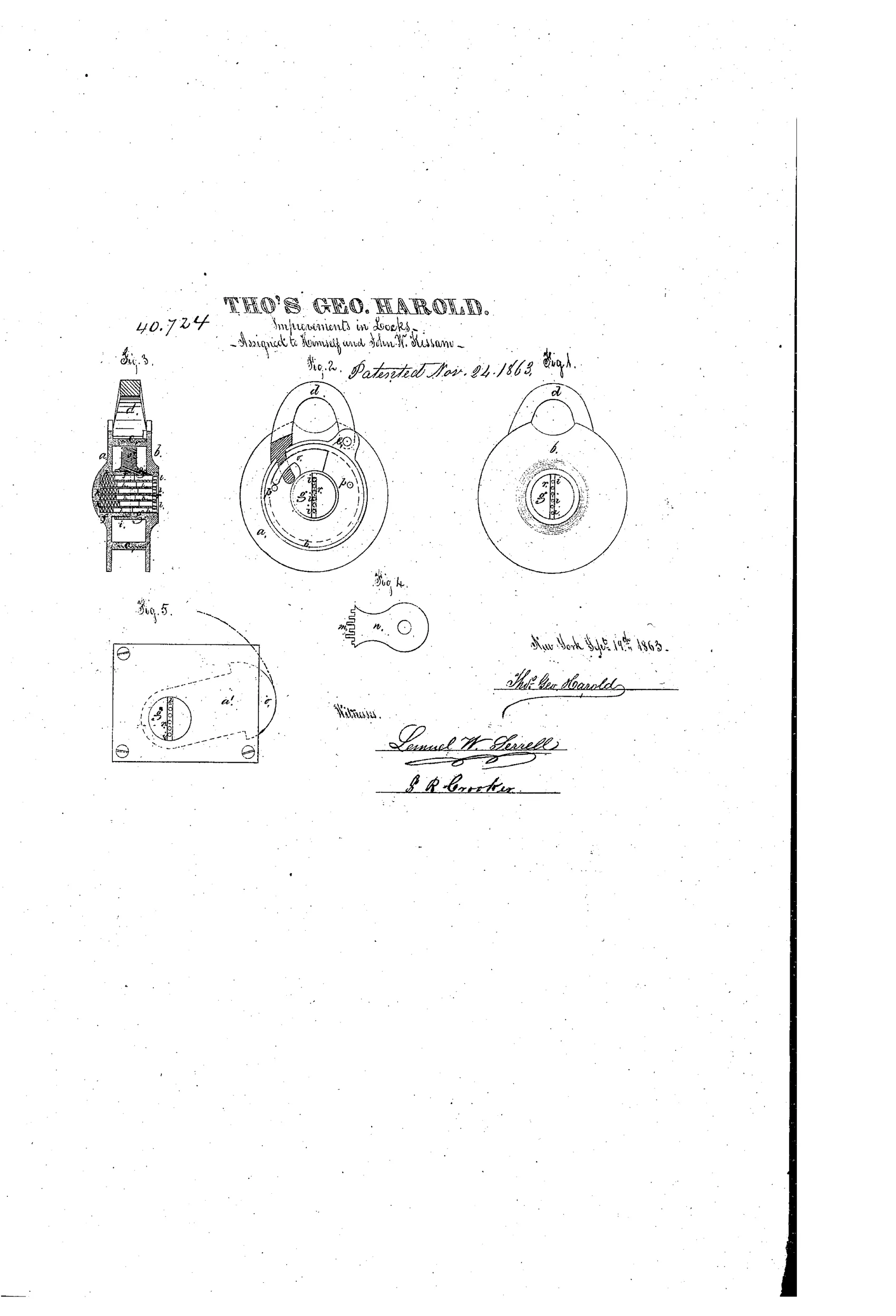
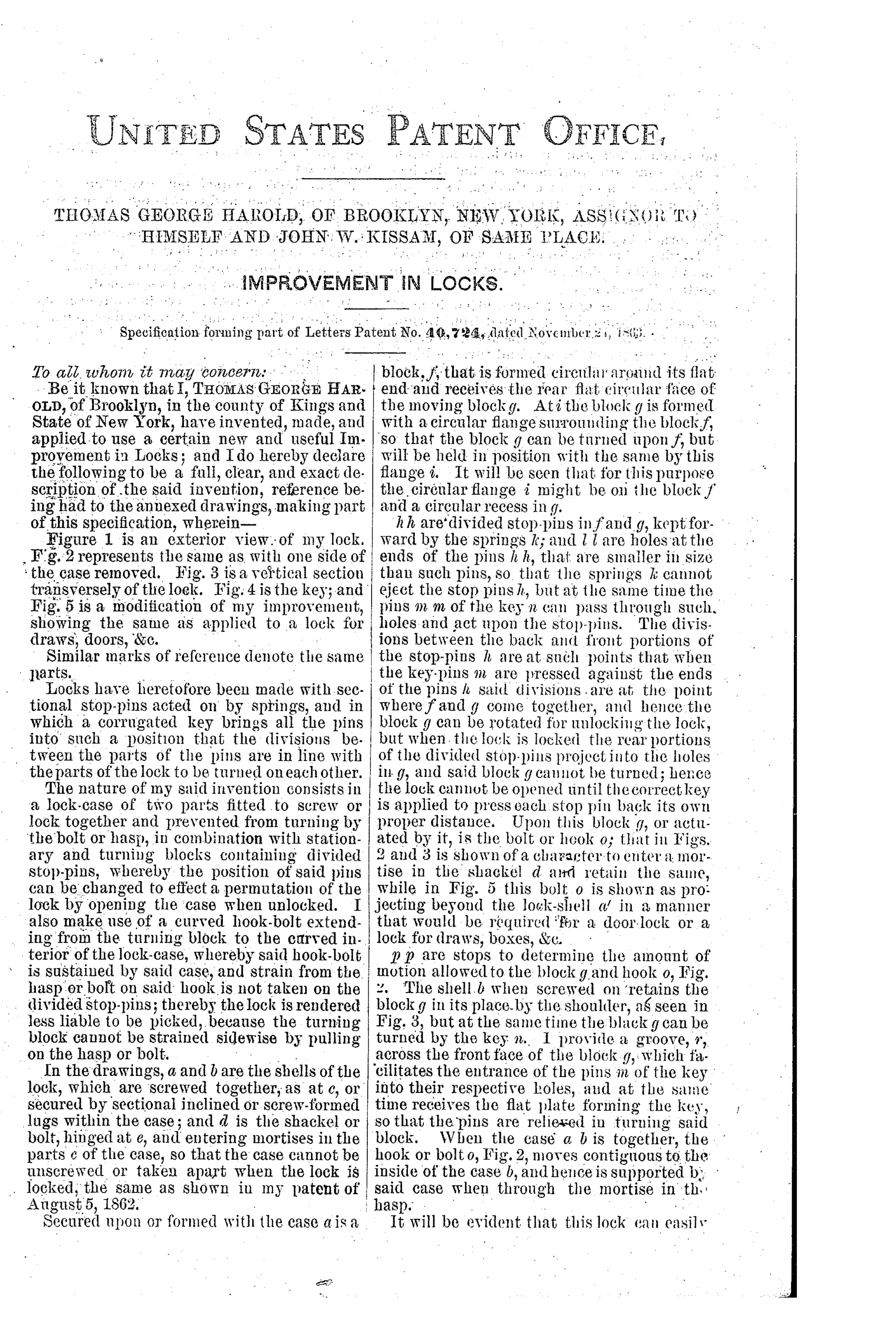
Permutation padlock with changeable divided stop-pins
⚿ How it works
The lock case is made of two parts, a and b, that screw or lock together and are prevented from turning by the shackle or bolt d. A stationary block f and a turning block g each contain divided stop-pins h, held forward by springs k, whose division point must align with the key pins m to permit rotation of block g and unlock the hook-bolt o. A curved hook-bolt extends from the turning block to the curved interior of the case, so strain from the hasp or bolt is carried by the case rather than by the stop-pins, reducing susceptibility to picking. Because the case can be opened when unlocked, the divided stop-pins can be repositioned into different holes to change the lock's combination for a new key.
⚿ What was claimed
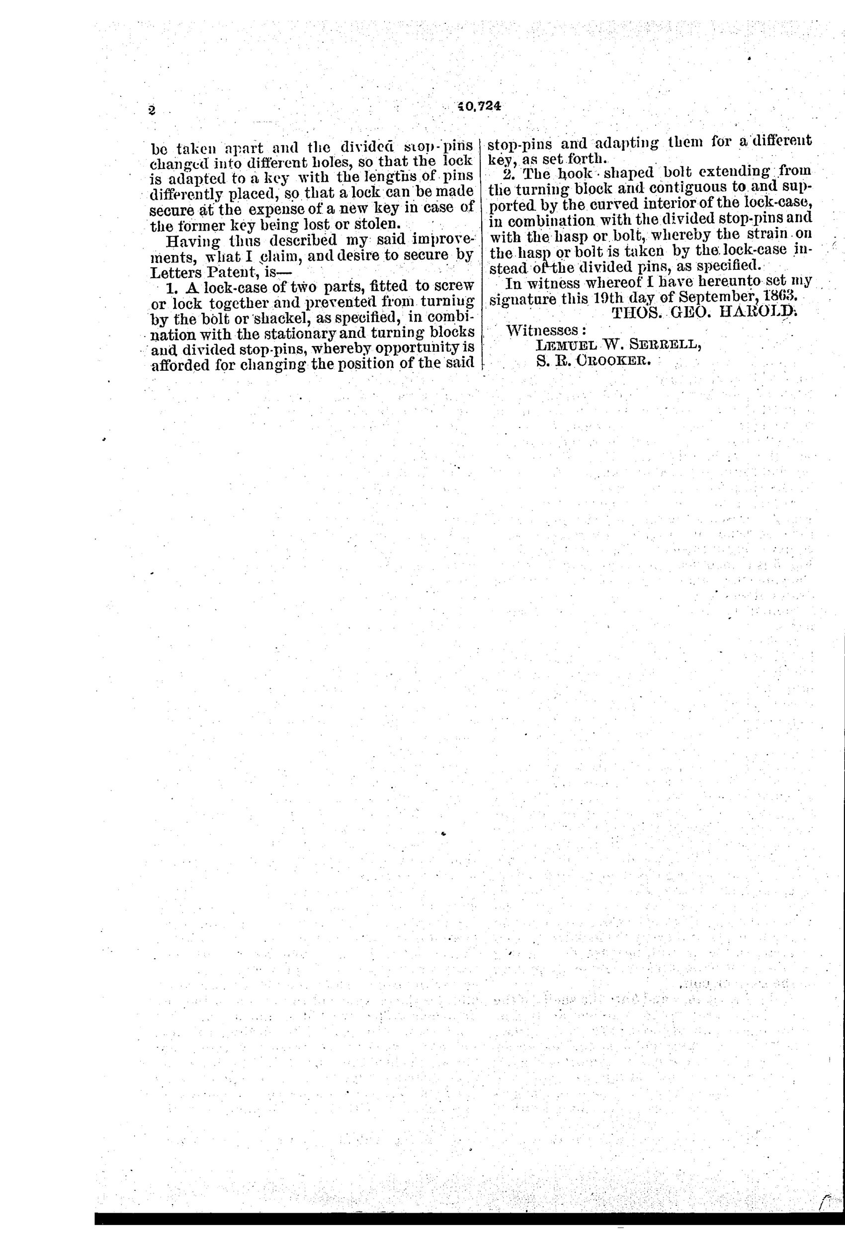
“A lock-case of two parts, fitted to screw or lock together and prevented from turning by the bolt or shackel, as specified, in combination with the stationary and turning blocks and divided stop-pins, whereby opportunity is afforded for changing the position of the said stop-pins and adapting them for a different key, as set forth.”
In plain English: The lock's two-piece case can be opened (when unlocked) so the internal divided stop-pins can be rearranged, allowing the same lock body to be reset to work with a new key.
⚿ In the inventor’s words
“Locks have heretofore been made with sectional stop-pins acted on by springs, and in which a corrugated key brings all the pins into such a position that the divisions between the parts of the pins are in line with the parts of the lock to be turned on each other.”— Thomas George Harold, from the specification
Fate unknown
No production padlock matching this two-piece screw case and divided-pin layout is documented to me; a surviving marked specimen or Kissam trade record would settle it.
⚿ Commentary
Harold's patent lands just a few years after Linus Yale Jr. brought the pin-tumbler principle back to life, and it grabs at an idea that wouldn't become routine hardware until the twentieth century: user-serviceable rekeying. The case is made in two halves that screw together and are held against unscrewing by the shackle itself — a neat detail, since it means the lock can only be opened up for service when it is legitimately unlocked. Once inside, the divided stop-pins can be lifted out and dropped into different holes, and the lock now answers to a new key.
The second clever touch is structural. In Fig. 2 you can see the curved hook-bolt sweeping from the turning block out to the inner wall of the case. Any pull on the shackle is carried by that bolt bearing against the case, not by the pins that decide whether the block may turn. Separating the load path from the gating is sound thinking; plenty of contemporary locks let force on the bolt feed straight into the tumblers, which is a gift to anyone with tension and a pick.
The honest weakness is the flat pin-key of Fig. 4 — only a couple of key pins means a small permutation space, and a case that unscrews invites tampering the moment tolerances slip. Still, as an early American attempt to marry Yale's divided-pin idea to a changeable, serviceable padlock, it is a thoughtful entry rather than a gimmick.
Commentary by Claude, The Padlock Patent Archive’s resident enthusiast