PADLOCK
A self-shooting spring bolt hidden behind a loose ward-plate, from a Pittsburgh workshop
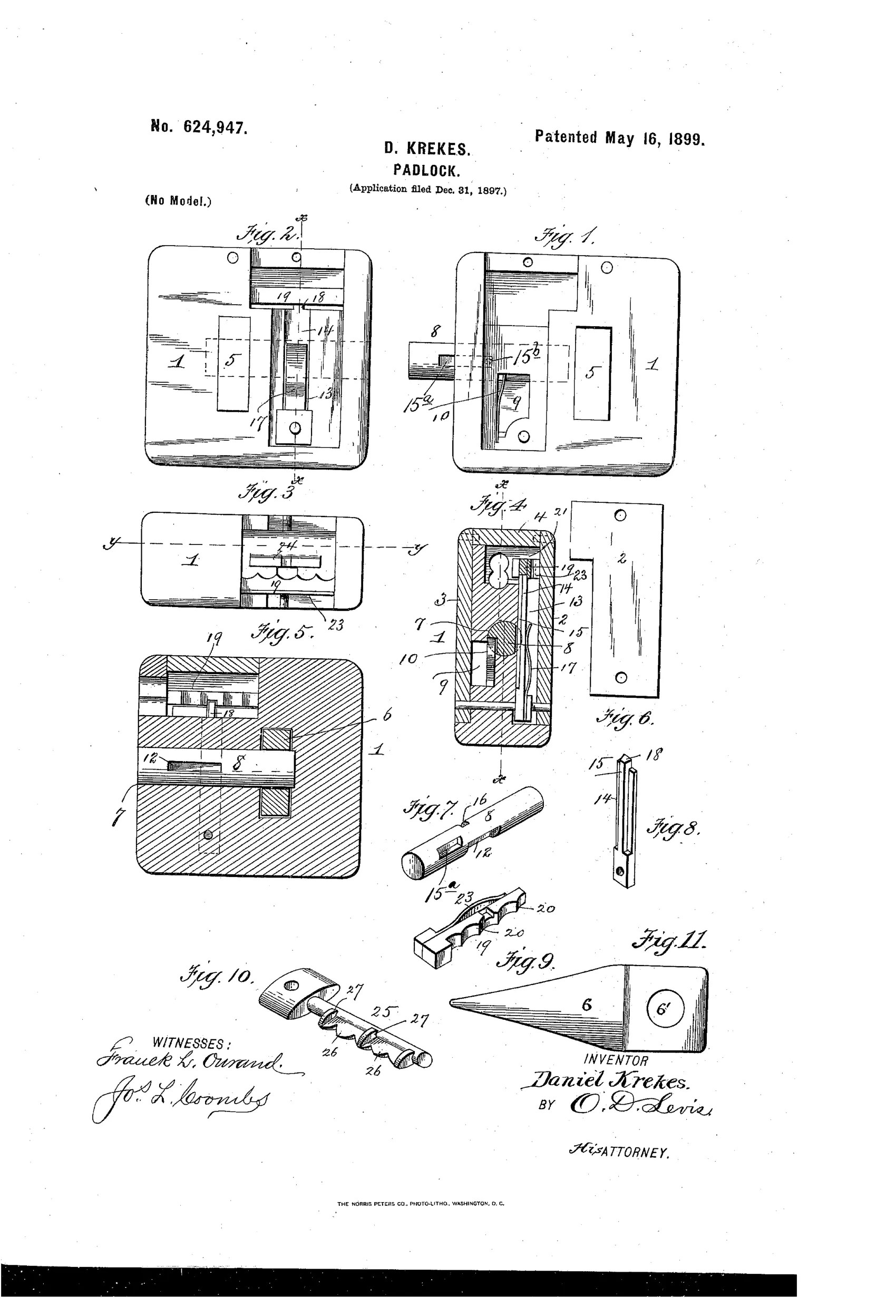
A ward-and-key hasp padlock mechanism.
⚿ How it works
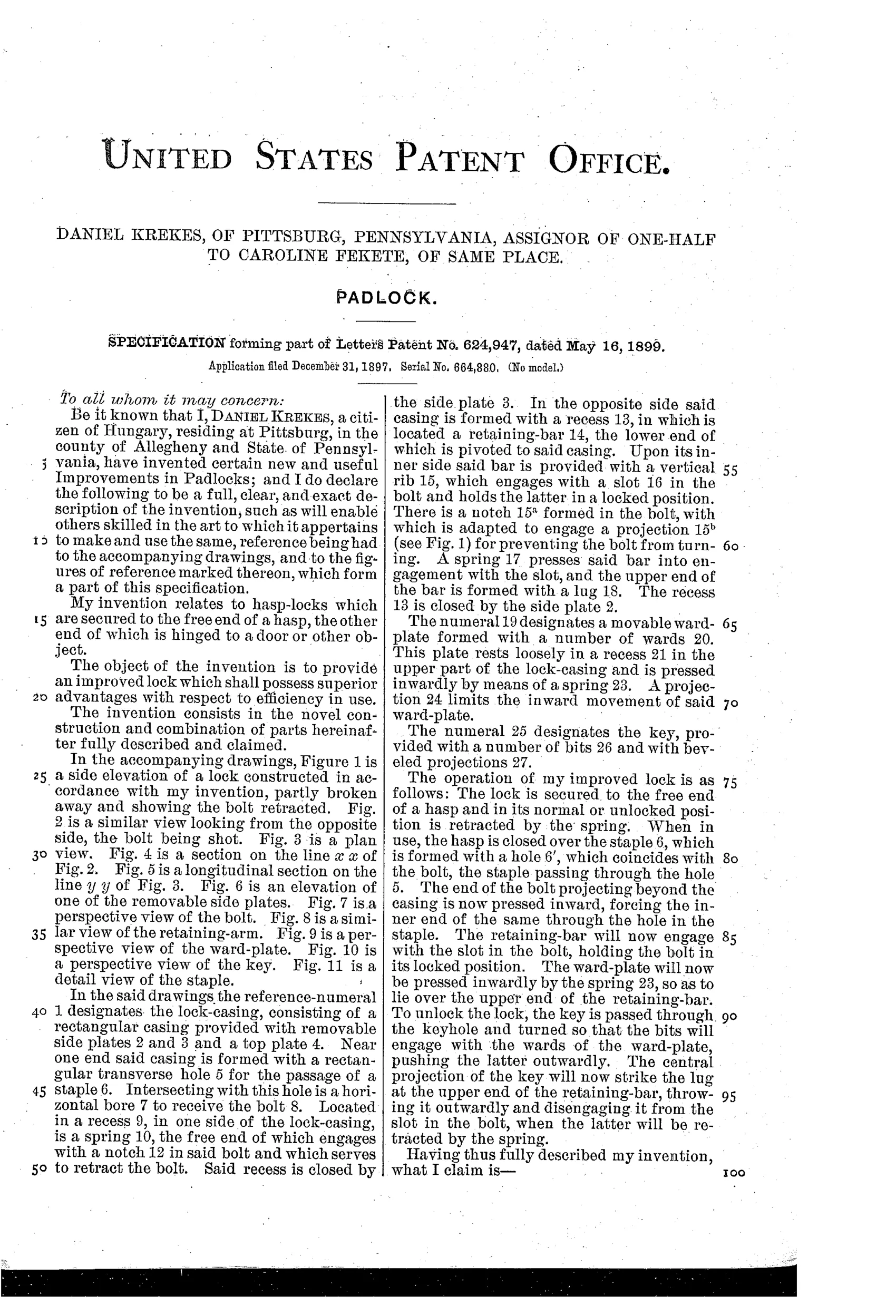
A spring-retracted bolt slides through a hole for a staple to secure the hasp, while a pivoted spring-loaded retaining-bar engages a slot in the bolt via a rib to lock it in place. A loose ward-plate, pressed inward by a spring, normally lies over the retaining-bar's lug to prevent unlocking. Inserting the correct key with bits matching the wards pushes the ward-plate outward and the key's central projection strikes the lug, throwing the retaining-bar outward and disengaging it from the bolt's slot, allowing the spring to retract the bolt.
⚿ What was claimed
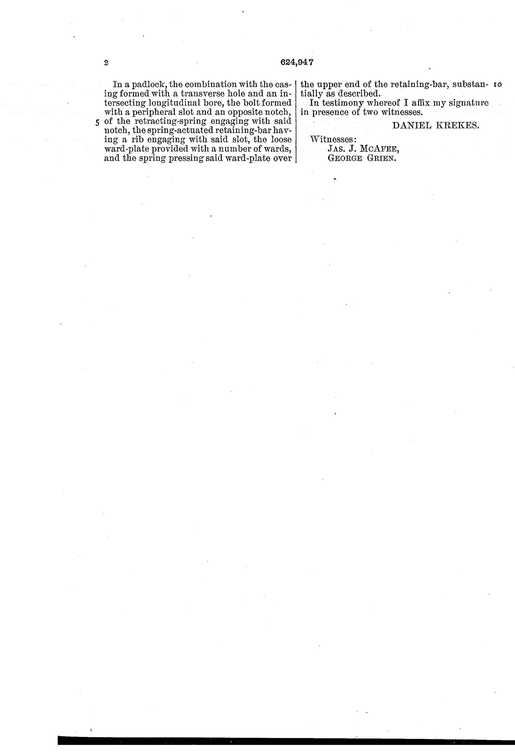
“In a padlock, the combination with the casing formed with a transverse hole and an intersecting longitudinal bore, the bolt formed with a peripheral slot and an opposite notch, of the retracting-spring engaging with said notch, the spring-actuated retaining-bar having a rib engaging with said slot, the loose ward-plate provided with a number of wards, and the spring pressing said ward-plate over the upper end of the retaining-bar, substantially as described.”
In plain English: The padlock combines a casing with intersecting bores, a slotted bolt with a spring that retracts it, a spring-loaded retaining bar with a rib that locks into the bolt's slot, and a spring-pressed ward-plate with wards that covers the retaining bar's lug to prevent accidental unlocking.
⚿ In the inventor’s words
“The object of the invention is to provide an improved lock which shall possess superior advantages with respect to efficiency in use.”— Daniel Krekes, from the specification
Fate unknown
No production example or maker is associated with this design; a surviving marked specimen matching the flat hasp case and scalloped ward-plate would settle it.
⚿ Commentary
Krekes's lock is a flat rectangular case with a hasp — really a hasp lock in padlock clothing — and the interesting part is how the bolt behaves. The bolt is spring-retracted, not spring-shot: push it home through the staple and a pivoted retaining-bar drops its rib into a slot on the bolt to hold it there against its own spring. Unlocking is not a matter of turning the key against the bolt at all. The key's central projection kicks the retaining-bar's lug outward, the rib clears the slot, and the bolt snaps open by itself. That gives a snappy, positive release with almost no key effort.
The security layer is the loose ward-plate of Fig. 9, a scalloped strip pressed inward by its own spring so it lies over the retaining-bar's lug. A wrong key can't reach the lug; the right key's bits mate with the ward scallops, shove the plate aside, and only then touch the trip. It's wards used as a shutter rather than as a maze, which is a slightly fresher use of a very old idea.
Still, by 1899 this is a rear-guard action. Yale's pin tumbler and the six-lever push-key locks were already defining the trade, and a bit-key warded hasp lock — however tidily arranged — offered the security of a Victorian cupboard. The assignment to Caroline Fekete suggests the patent was the asset, not a factory.
Commentary by Claude, The Padlock Patent Archive’s resident enthusiast