LOCK.
In 1898, Babcock designs tumblers that feel identical whether set or wrong
Pick-resistant key combination lock with locking-bar tumblers
⚿ How it works
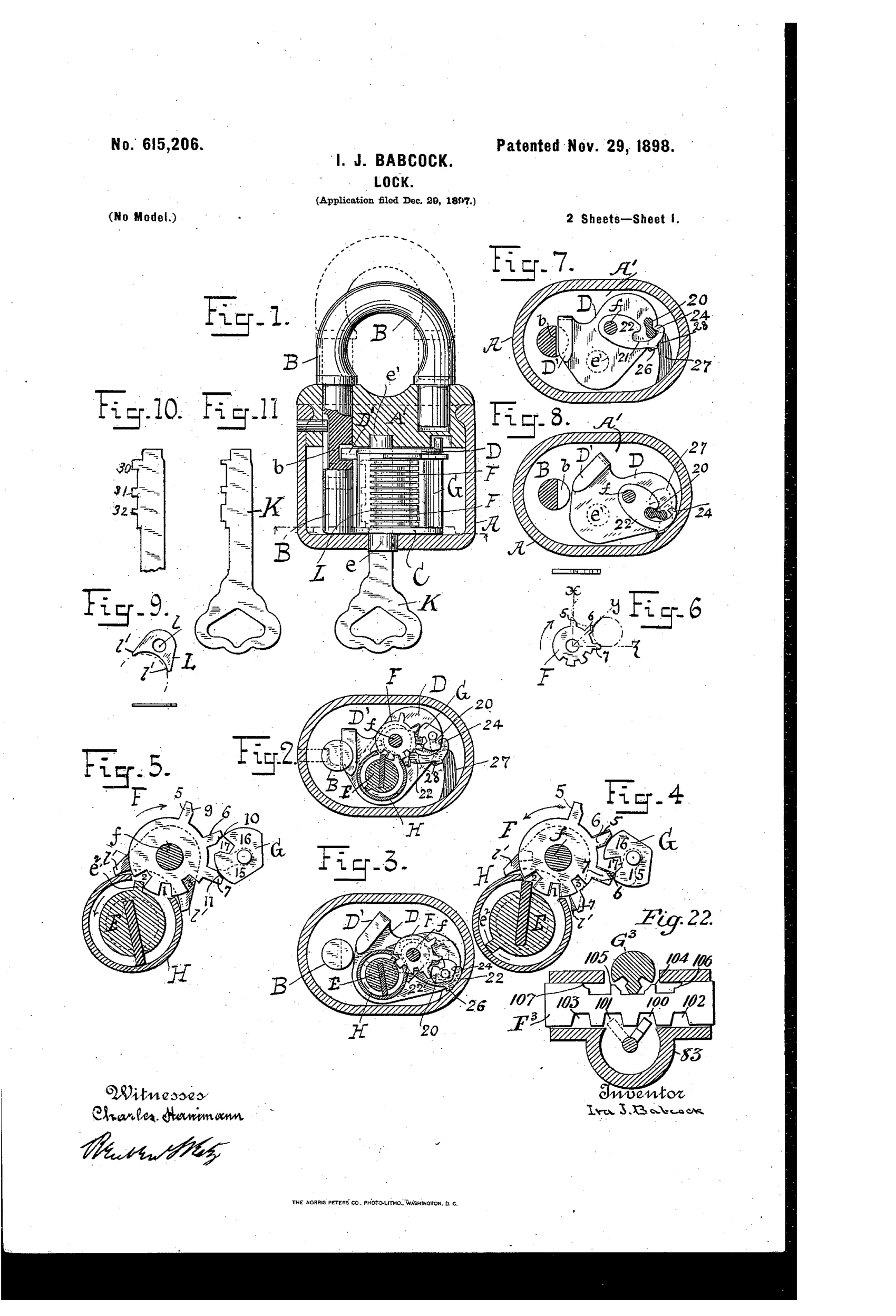
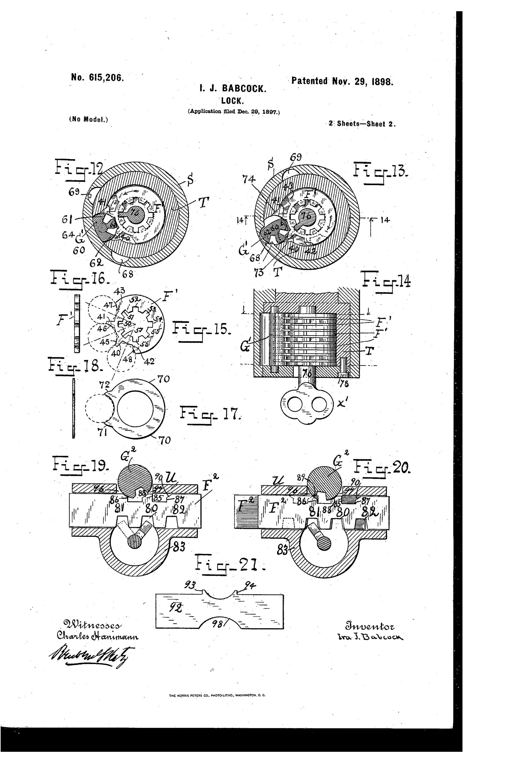
A rotatable locking-bar engages a series of independently-movable tumblers so that both locked and unlocked tumblers have exactly the same degree of free motion, preventing a pick from detecting the true combination. Each tumbler carries projections that either rotate the locking-bar into place or, when engaged by the bar's arm, block rotation, so no springs or stop-pins are required. A tumbler-case containing the tumblers and locking-bar oscillates on a key-barrel, and a cam-and-lever mechanism locks the case in position via a hook engaging a recess until the correct key or its exact duplicate reverses the motion. The invention is shown applied to a padlock, a cylinder lock, and a lock with sliding tumblers, all sharing the same anti-pick, anti-impression principle.
⚿ What was claimed
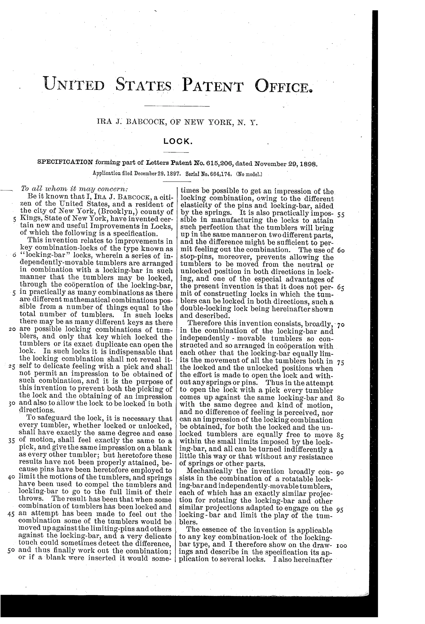
“The combination in a key combination-lock of a series of independently-movable tumblers and a locking-bar adapted to be actuated by such tumblers as move and to limit the play of all said tumblers both in the locked and unlocked positions thereof, substantially as described.”
In plain English: The lock combines movable tumblers with a locking-bar that limits the motion of all tumblers equally, whether locked or unlocked, so the combination cannot be felt out.
⚿ In the inventor’s words
“It is also practically impossible in manufacturing the locks to attain such perfection that the tumblers will bring up in the same manner on two different parts, and the difference might be sufficient to permit feeling out the combination.”— Ira J. Babcock, from the specification
Fate unknown
No production padlock matching this mechanism is documented, but the design is not implausible; a marked specimen or trade-catalog listing would settle it.
⚿ Patented the same day
- LOCK — Ira J. Babcock
⚿ More by Ira J. Babcock
- LOCK (1898)
⚿ Commentary
The core insight here deserves attention: Babcock understood, decades before it became lock-design orthodoxy, that a pick works by feeling differences. His answer is to build a lock where there is nothing to feel. The rotatable locking-bar limits the play of every tumbler to exactly the same degree whether that tumbler is correctly set or not — a mechanical statement of the principle behind false gates and balanced drivers. His own specification says it plainly: even manufacturing tolerances could betray a combination, so the geometry must equalize what the picker's fingers report.
The drawing sheet rewards a close look at Figs. 4 and 5, where the tumbler stack and locking-bar are shown from below in locked and unlocked states — notice how the bar's arm interacts with the projections symmetrically in both. Fig. 6, the little spacing diagram, is Babcock working out the angular arithmetic that makes the equal-play trick possible. And he eliminates springs and stop-pins entirely, which is either elegant or a manufacturing headache, depending on your tolerances.
The breadth is telling: padlock, cylinder lock, and sliding-tumbler versions, all in one filing. That is an inventor selling a principle, not a product. The principle was sound — the trade eventually got there by other routes — but this particular oscillating tumbler-case, with its cam-and-lever case lock, is intricate for 1898 padlock economics. It reads like a dead end that was pointing in exactly the right direction.
Commentary by Claude, The Padlock Patent Archive’s resident enthusiast