LOCK
The tumbler cylinder is the bolt: shackle grabbed at both ends, no linkage
Key combination padlock with rotating tumbler cylinder bolt
⚿ How it works
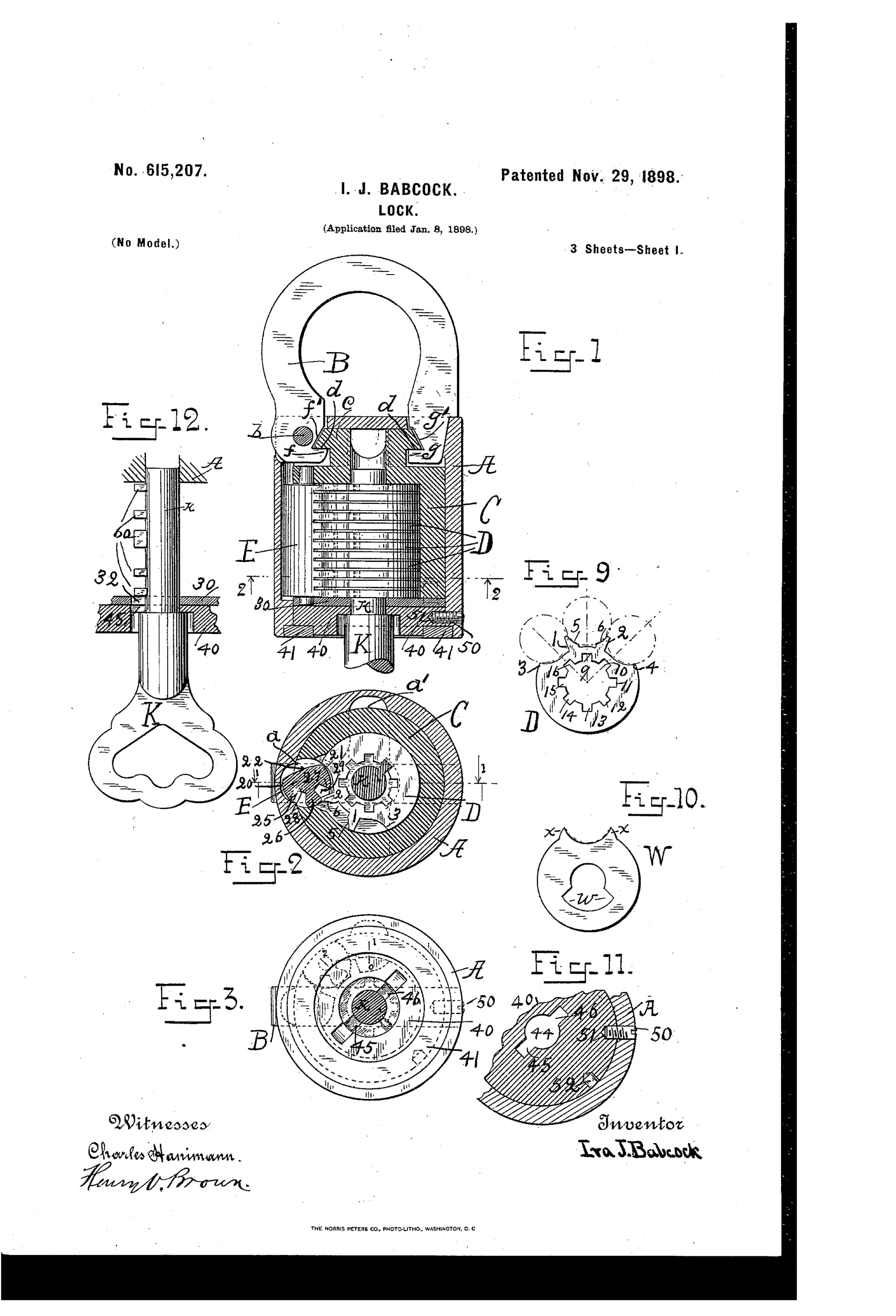
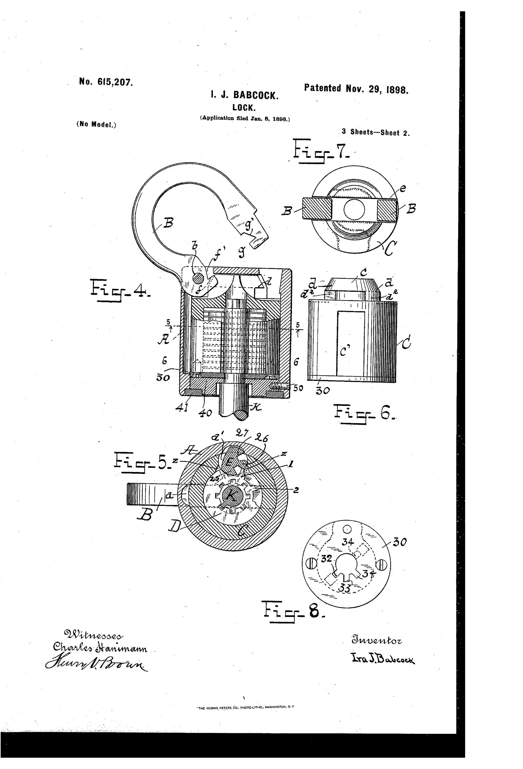
A rotatable tumbler-case (cylinder) carries a locking-bar that engages a series of independently-movable tumblers, each with multiple projections that turn the locking-bar to different positions as the key rotates. The tumbler-case itself forms an integral bolt that engages hooks on the shackle directly, without any intermediary bolt part, locking the shackle at both ends. The lock can be set to lock in two different rotational directions, always leaving some combination of tumblers in a locked position even when the shackle is open, preventing tampering by unauthorized key insertion. A removable head and shiftable cap with multiple key-slots prevent withdrawal of the key unless tumblers are in a locking combination, and allow the combination to be changed only by the rightful key holder.
⚿ What was claimed
“In a lock adapted for locking in two directions, the combination of a rotatable locking-bar and a series of independently-rotatable tumblers, each provided with a plurality of projections adapted to rotate said locking-bar and to engage on said locking-bar and limit the motion of said tumblers, substantially as described.”
In plain English: The lock uses a turnable locking bar together with several independently rotating tumblers, each having projections that both turn the bar and limit how far the tumblers can move.
⚿ In the inventor’s words
“Practically the change is impossible to any except the rightful owner.”— Ira J. Babcock, from the specification
Paper patent — likely never produced
No known production example matches this design, and the part count and lack of an assignee make manufacture implausible; a marked specimen would overturn this.
⚿ Patented the same day
- LOCK. — Ira J. Babcock
⚿ More by Ira J. Babcock
- LOCK. (1898)
⚿ Commentary
Babcock's central idea is worth slowing down for: instead of the key operating tumblers that release a separate bolt, the whole tumbler-case rotates and its body directly hooks the shackle at both heel and toe. Fig. 1 shows this plainly — the stacked disc tumblers ride inside the cylinder, and the cylinder itself is the moving part that captures the shackle. Deleting the intermediate bolt removes the classic attack point where you pry or rap the bolt out of engagement, and locking both shackle ends means you can't spring one leg free.
The second idea is subtler and shows up in Fig. 12: a shiftable cap with multiple key-slots that refuses to release the key unless the tumblers sit in a locking combination. Even with the shackle open, some tumblers always remain set, so an interloper can't insert a trial key and read the lock at leisure. Add the owner-only combination change and you have a padlock that thinks like a safe lock — this is really a disc-permutation mechanism dressed as a keyed padlock.
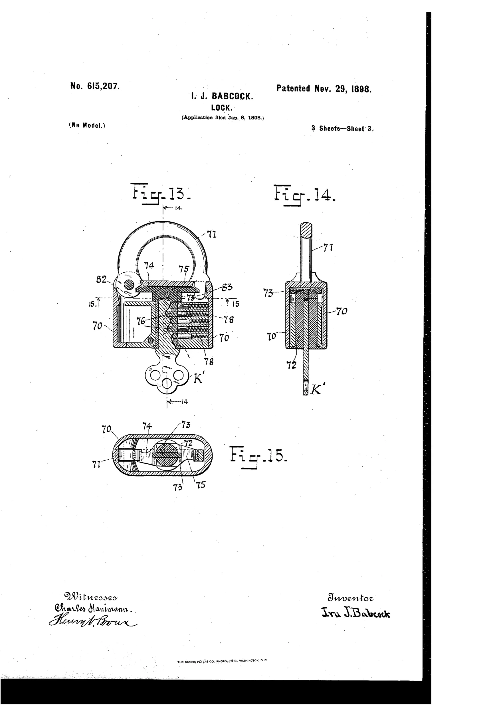
The cost is complexity. Fifteen figures, stacked tumblers each with multiple projections, removable heads, shiftable caps, plus a pin-tumbler variant tacked on in Figs. 13-15 as insurance. That's a lot of precision parts for 1898 padlock money, and no assignee is named to pay for tooling. Clever engineering, doubtful economics — the recurring story of the keyless-permutation corner of this field.
Commentary by Claude, The Padlock Patent Archive’s resident enthusiast