IMPROVEMENT IN PADLOCKS
Both shackle legs come out: three latch pairs on one central pin
A detachable-hasp padlock with cross-latches
⚿ How it works
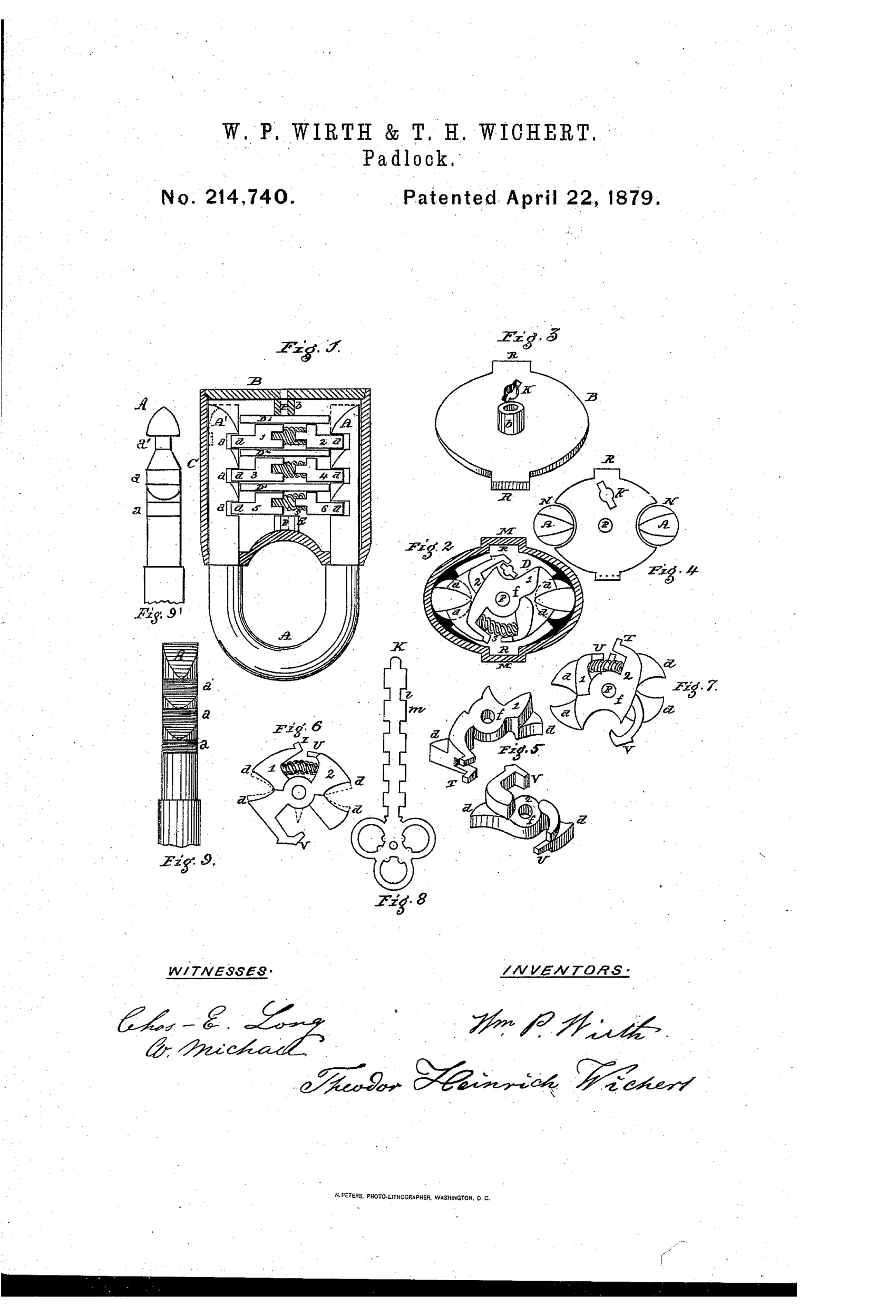
The lock uses a detachable notched shackle with legs that insert into a shell containing three stacked pairs of cross-latches, each pair pivoting on a single central pin. Each latch has gripe or jaw ends and a central annular opening; the pairs are separated by horizontal cross-plates and act on the shackle notches to lock it in place. A coiled spring between projecting flanges (T and V) on each latch pair forces the gripes into the shackle notches, while a key inserted through side keyholes presses the latches apart via lever projections to withdraw the gripes and release the shackle. Reinserting the shackle legs pushes the wedge-shaped notch portions against the jaws, forcing them outward and then letting the springs snap them back into the notches to relock.
⚿ What was claimed
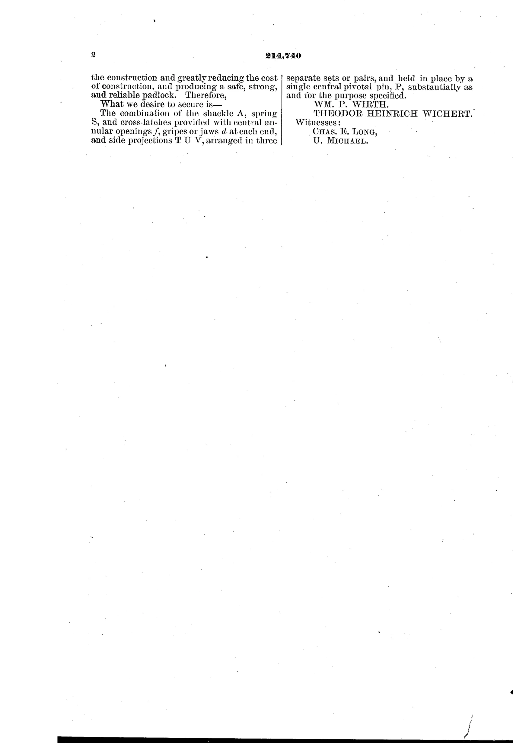
“The combination of the shackle A, spring S, and cross-latches provided with central annular openings f, gripes or jaws d at each end, and side projections T U V, arranged in three separate sets or pairs, and held in place by a single central pivotal pin, P, substantially as and for the purpose specified.”
In plain English: The claim covers a padlock shackle combined with a spring and three pairs of cross-latches, each latch having a central hole, gripping ends, and side projections, all held together by one central pivot pin.
⚿ In the inventor’s words
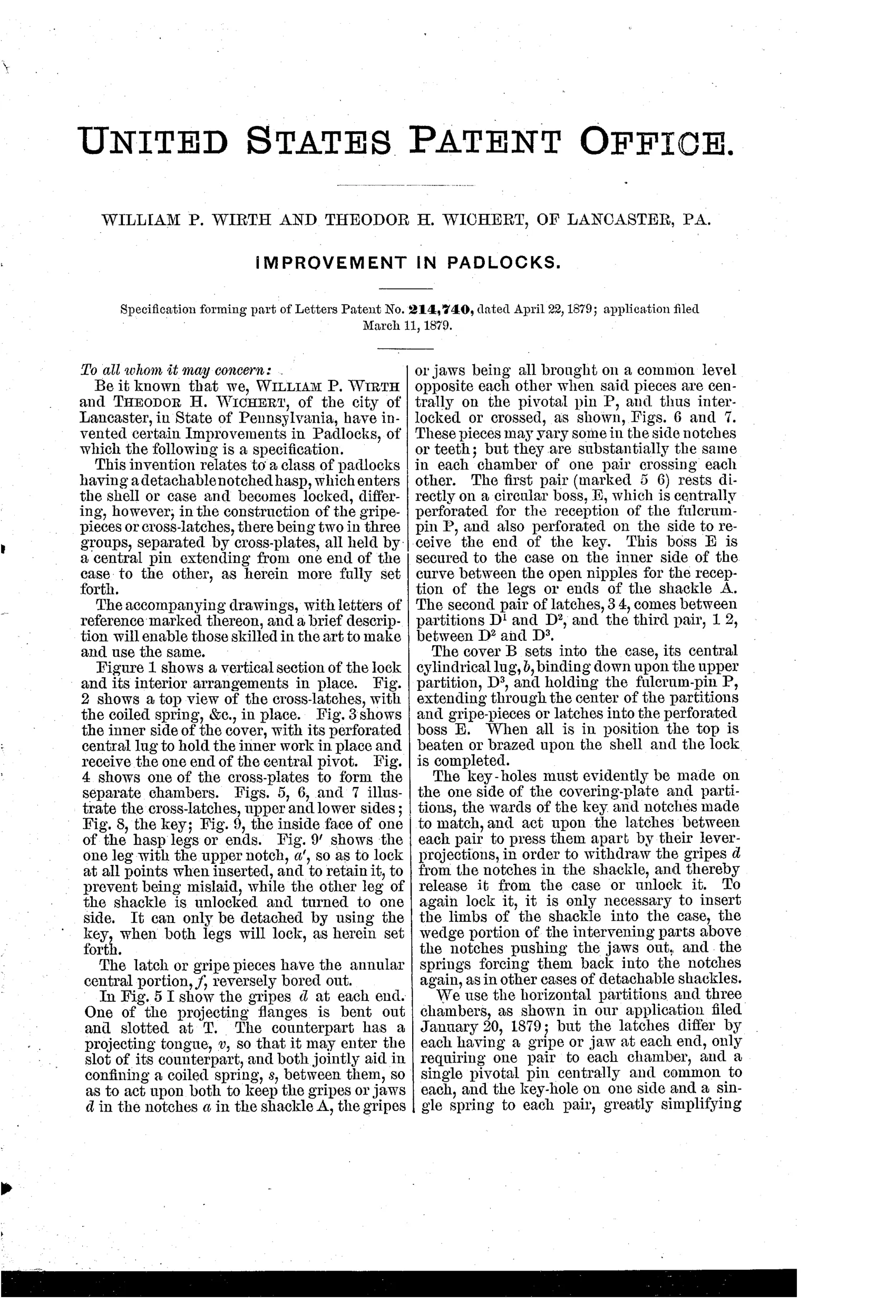
“We use the horizontal partitions and three chambers, as shown in our application filed January 20, 1879; but the latches differ by each having a gripe or jaw at each end, only requiring one pair to each chamber, and a single pivotal pin centrally and common to each, and the key-hole on one side and a single spring to each pair, greatly simplifying the construction and greatly reducing the cost of construction, and producing a safe, strong, and reliable padlock.”— William P. Wirth and Theodor Heinrich Wichert, from the specification
Fate unknown
The inventors' explicit cost-reduction rework hints at production intent, but no marked specimen is documented; a surviving example from a Lancaster maker would settle it.
⚿ Patented the same day
- IMPROVEMENT IN PADLOCKS — Theodor Heinrich Wichert
⚿ Commentary
Most padlocks pivot or slide one end of the shackle; Wirth and Wichert throw the whole shackle away. Both legs pull free of the case, each leg notched like a crude rack, and inside three stacked chambers three pairs of scissor-like cross-latches snap their jaws into those notches under coil-spring pressure. The genuinely tidy bit is the single central pivot pin carrying all six latches — one rivet does the work that a conventional lever lock would spread across a whole gate-and-fence assembly.
The relocking action is the part worth studying in Fig. 1 and Fig. 9: the notch faces on the shackle legs are wedge-shaped, so shoving the shackle home cams the jaws apart and lets the springs slam them back in. That means the lock is self-latching without the key, a feature buyers actually valued. The key, entering from the side, simply levers the latch pairs apart against their springs — no tumbling, no gating, so security rests almost entirely on the wards of the key in Fig. 8, which is thin protection.
This is the pair's second try in three months; they say so themselves, boasting that double-ended jaws halved the parts count of their January filing. That candor about cost-cutting suggests they were chasing manufacture, not just a certificate. But detachable-shackle designs mostly lost out to the pivoting shackle, and this one left no obvious commercial trace.
Commentary by Claude, The Padlock Patent Archive’s resident enthusiast