PADLOCK
A key that hides its own bit, folded inside a tube from Pomerania
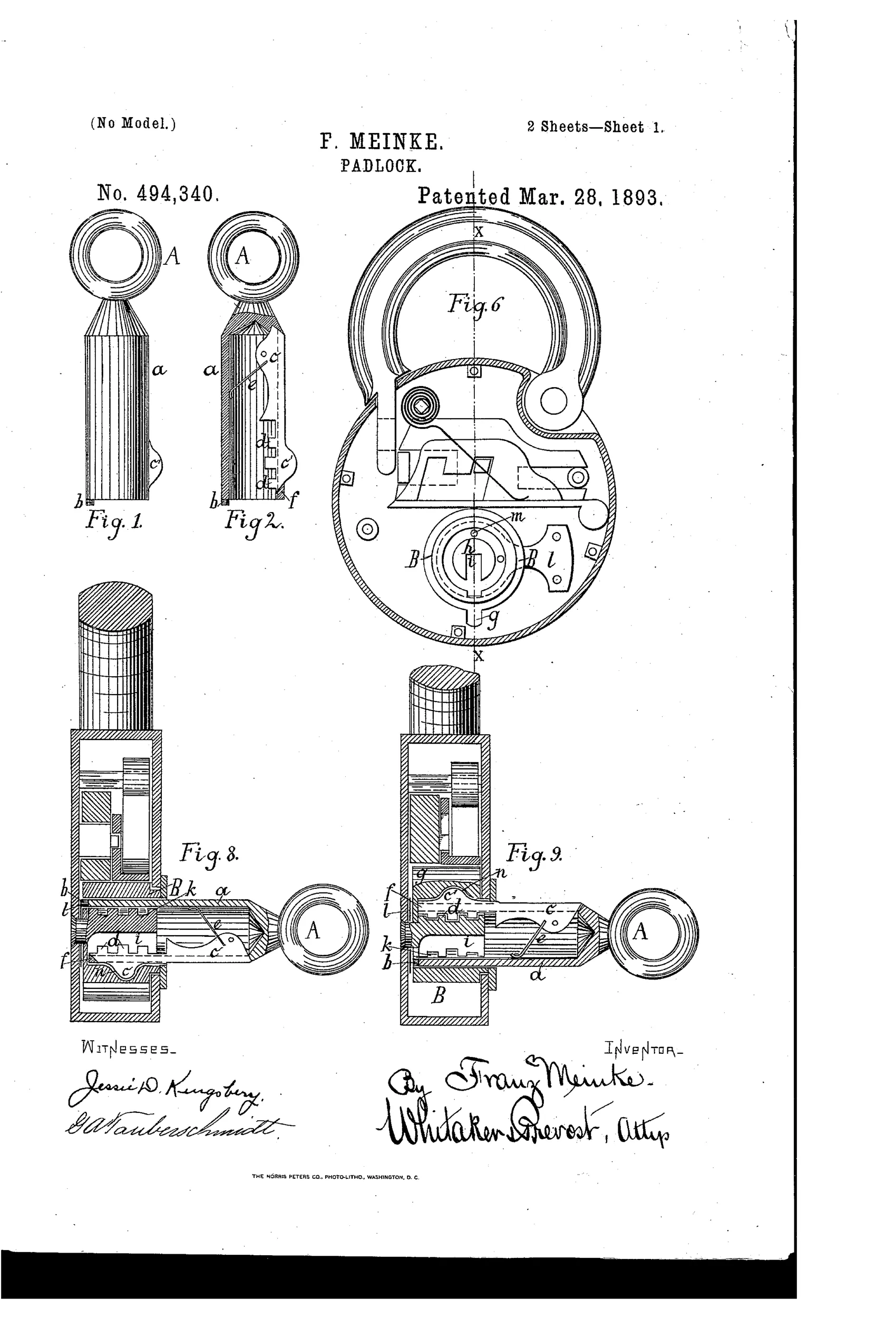
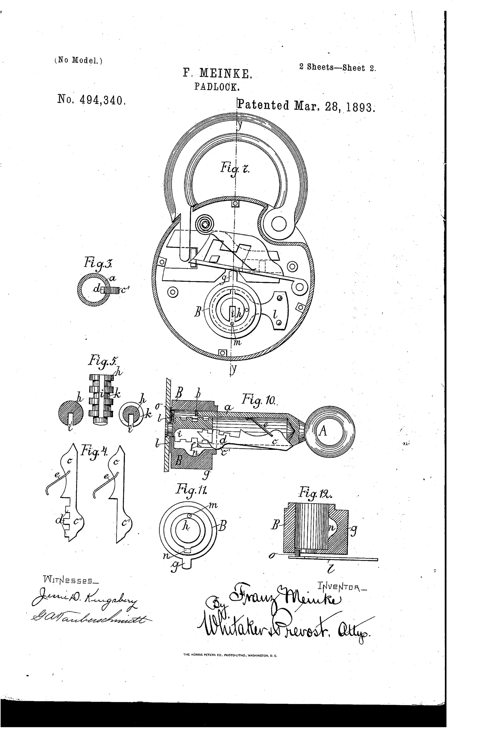
Master-keyed padlock with pivoted key bit
⚿ How it works
The key A has a tubular body with a pivoted, spring-loaded bit c that folds against the pipe when inserted. The bit engages grooves cut into a fixed corrugated key-pin post h, so only a matching key can rotate a hollow boss B surrounding the post. Rotating the boss engages a shoulder g with the lock bolt to lock or unlock it, while a projection on the bit locks into a recess in the boss to transmit rotation. A master key is made by using a bit without the ward-matching projections, allowing it to turn freely on any post regardless of its particular wards; an additional pin-and-stop arrangement in the boss end plate further guards against picking.
⚿ What was claimed
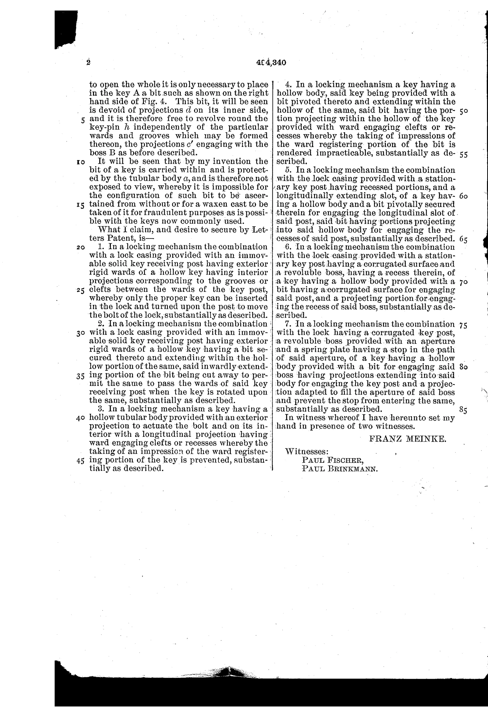
“In a locking mechanism the combination with a lock casing provided with an immovable solid key receiving post having exterior rigid wards of a hollow key having interior projections corresponding to the grooves or clefts between the wards of the key post, whereby only the proper key can be inserted in the lock and turned upon the post to move the bolt of the lock, substantially as described.”
In plain English: The lock combines a fixed, ridged key post inside the casing with a hollow key whose interior grooves match those ridges, so only the correctly cut key can be inserted and turned to move the bolt.
⚿ In the inventor’s words
“It will be seen that by my invention the bit of a key is carried within and is protected by the tubular body a, and is therefore not exposed to view, whereby it is impossible for the configuration of such bit to be ascertained from without or for a waxen cast to be taken of it for fraudulent purposes as is possible with the keys now commonly used.”— Franz Meinke, from the specification
Paper patent — likely never produced
The folding-bit key is costly and delicate for a padlock, and no production example matching this design is documented; a surviving specimen would change the call.
⚿ Commentary
Franz Meinke's answer to the wax-impression thief is genuinely inventive: the key's bit is pivoted and spring-loaded inside a hollow tubular body, so it folds flat during insertion and only swings out to engage the wards once inside the lock. His own specification makes the point plainly — you can't take a cast of a bit you can never see. Figures 1 and 2 show the trick well: from outside, every key looks like the same smooth pipe with an eye on the end.
The locking itself is a clever inversion of ordinary warding. Instead of wards fixed in the keyway, the lock has a fixed corrugated post (Fig. 5) standing inside a rotating hollow boss. The hollow key slides over the post, its interior projections must match the post's grooves, and only then can it turn the boss whose shoulder throws the bolt. Master keying falls out naturally — omit the projections and the key turns freely on any post — which is elegant, though it also means the master key is trivially simple to make, a security cost the specification doesn't dwell on.
Mechanically it should work, but it's fussy: a pivoted, sprung bit inside a small tube is a fragile, dirt-sensitive assembly for a padlock that lives outdoors. This sits in the 1890s wave of anti-copying key schemes that pin-tumbler locks would soon render moot — a thoughtful dead end rather than a foundation.
Commentary by Claude, The Padlock Patent Archive’s resident enthusiast