LOCK
The key turns a screw, cranking two jawed halves together like a vise
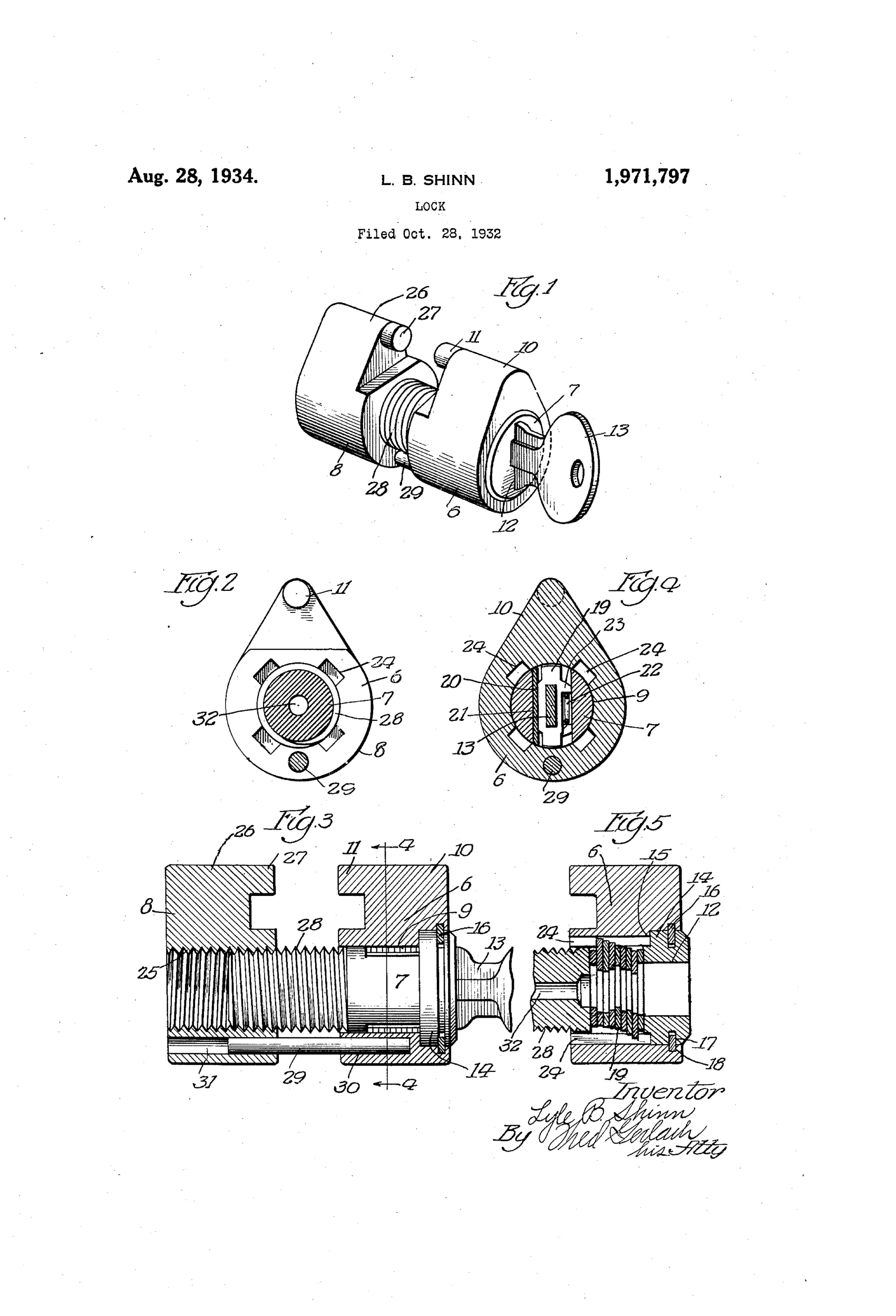
Padlock with screw-actuated complemental locking member
⚿ How it works
The lock has a main lock-member with a bore in which a key-operated plug rotates, and a complemental lock-member positioned behind it. A screw formed integrally with the plug's rear end engages an internally threaded bore in the complemental member, so turning the plug via the key shifts the complemental member toward or away from the main member. Opposite-facing jaws on the two members abut when shifted together, creating the locking engagement for an apertured element such as a hasp or staple. Spring-pressed plate tumblers in the plug engage longitudinal grooves in the main lock-member's bore to lock the plug against rotation whenever the key is removed, while a pin-and-socket connection prevents relative rotation between the two members and confines them to rectilinear movement.
⚿ What was claimed
“1. In a lock of the character described, the combination of a pair of elongated, complementary members arranged in end to end relation and embodying coacting lock-means and shiftable towards one another into a locking position wherein said means are rendered operative and away from one another into an unlocked position, one of said members having a bore extending longitudinally therethrough, a plug mounted rotatably, and confined against axial displacement, in the bore and provided with key-operable tumblers for locking it against rotation relatively to said one member, and also provided with a slot for the key in the end farthest from the other member, and a screw connected rigidly to and projecting from the other end of the plug and applied to said other member so that it operates in response to rotation of the plug in one direction to shift the members into locking position and in response to rotation of the plug in the opposite direction to shift the members into unlocked position.”
In plain English: A padlock made of two end-to-end members that lock together when a key-turned plug's built-in screw drives them toward each other, and unlocks them when turned the other way.
⚿ In the inventor’s words
“The herein described lock consists of but a small number of parts and may be manufactured at a low and reasonable cost.”— Lyle B. Shinn, from the specification
Fate unknown
Chicago Lock produced Shinn's other designs in quantity, but no marked example of this screw-jaw padlock is documented; a surviving specimen would settle it.
⚿ Commentary
Most padlocks lock with a snap: a spring bolt drops into a shackle notch and you're done. Shinn throws that out. Here the key doesn't release anything — it does the work. The plug carries an integral screw at its rear (visible in Fig. 3 as the threaded shaft running into the second member), and turning the key winds the two halves of the lock toward each other along that thread until their opposed jaws close on whatever apertured hasp or staple sits between them. Unlocking is the same motion in reverse. It's less a padlock than a key-operated clamp.
The quiet cleverness is in what keeps this honest. A pin-and-socket connection stops the rear member from simply spinning with the screw, forcing pure rectilinear travel. And the plate tumblers (Fig. 5) engage grooves in the housing bore whenever the key is out, so the plug — and therefore the screw — can't be turned by torque applied to the body. Attack the jaws and you're fighting thread engagement, not a spring bolt.
The trade-off is obvious: many key turns to open instead of one, which is why the industry stayed with snap-shut shackles. But for securing chains, valve wheels, or equipment where slow-and-strong beats fast, the screw approach has genuine merit. Chicago Lock's assignment, and Shinn's claim of few parts at low cost, suggest this was a serious commercial proposal, not a tinkerer's fancy.
Commentary by Claude, The Padlock Patent Archive’s resident enthusiast