IMPROVEMENT IN PADLOCK-CASES
Corrugated tin, not thick iron: cheap stamped shells that shrug off hammer blows
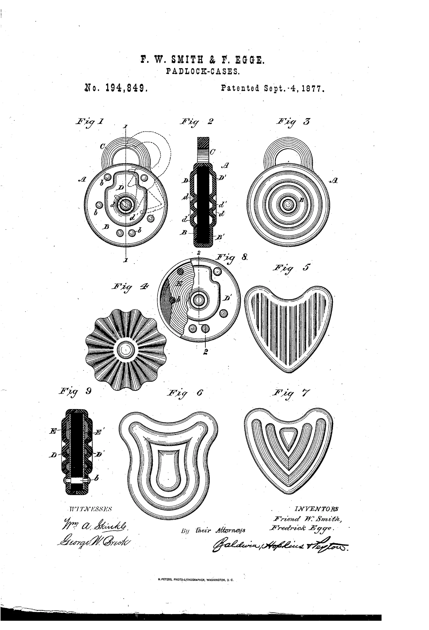
Corrugated sheet-metal padlock case design
⚿ How it works
The lock case is made of two stamped sheet-metal halves that are crimped or corrugated to form ribs and offsets, then riveted together. These corrugations strengthen the case and create raised areas that absorb blows, protecting the internal mechanism from being deformed by hammering. Central undisturbed bearing areas support the shackle extension to prevent wobbling. Internal smooth protecting plates may also be fitted inside the case to shield the works and provide a bearing surface, making the lock harder to pick.
⚿ What was claimed
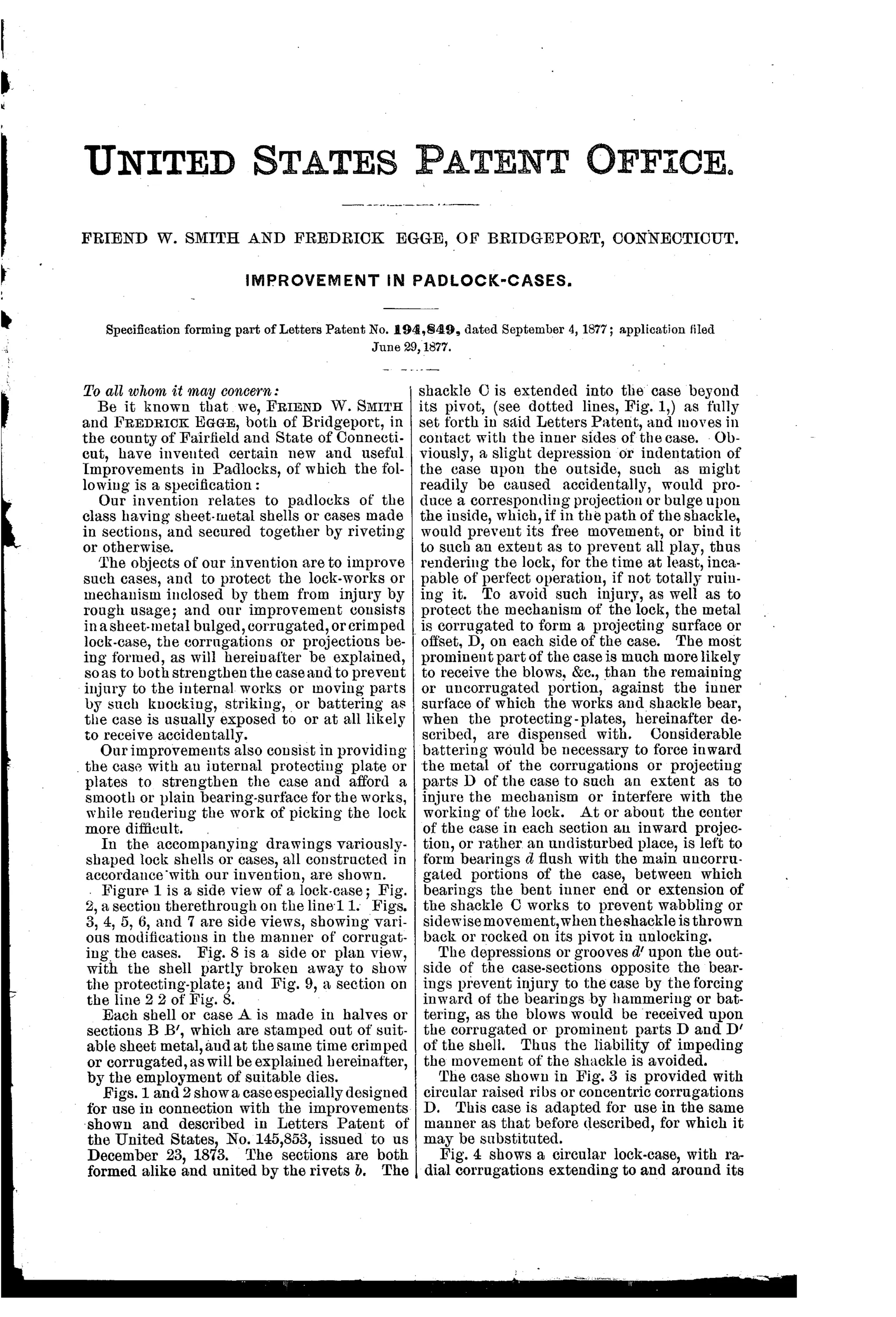
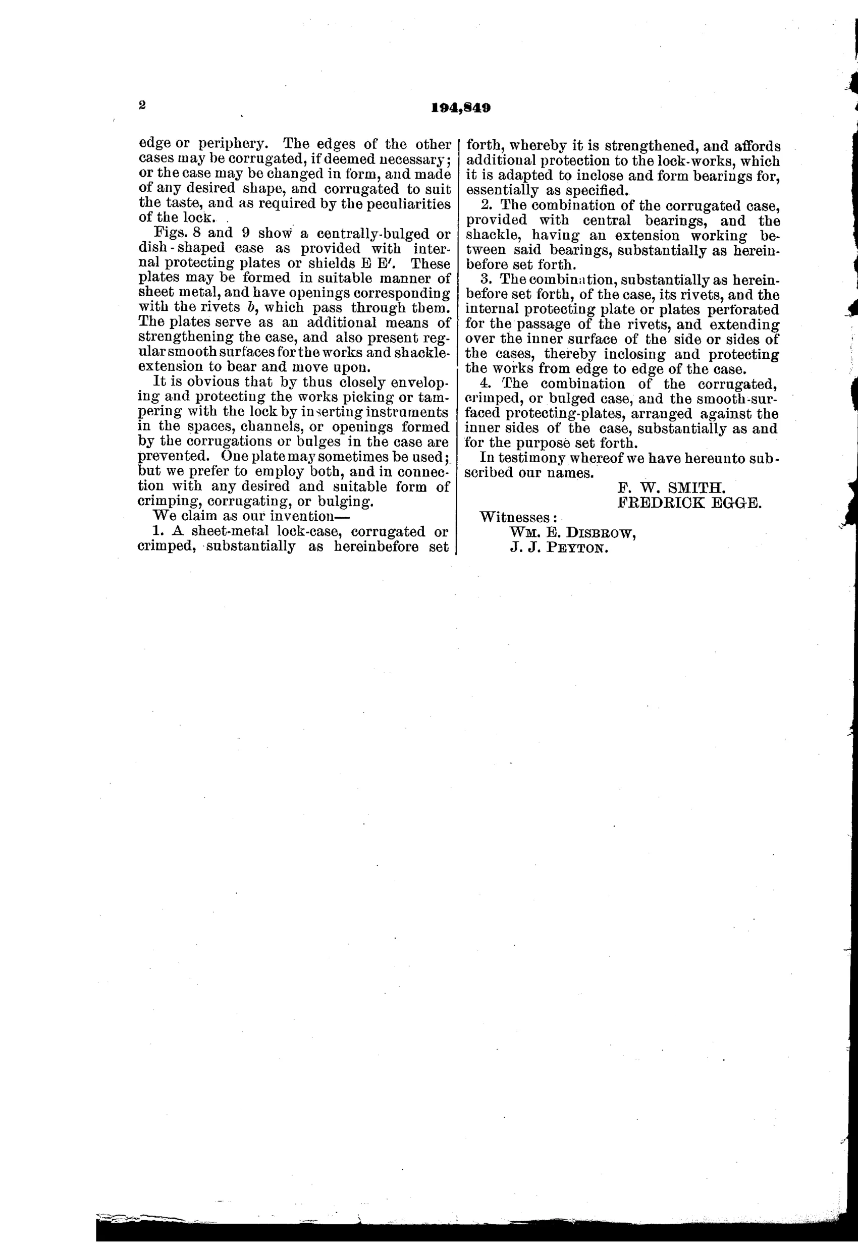
“1. A sheet-metal lock-case, corrugated or crimped, substantially as hereinbefore set forth, whereby it is strengthened, and affords additional protection to the lock-works, which it is adapted to inclose and form bearings for, essentially as specified.”
In plain English: A padlock case made of corrugated or crimped sheet metal that is stronger and protects the internal lock mechanism.
⚿ In the inventor’s words
“Considerable battering would be necessary to force inward the metal of the corrugations or projecting parts D of the case to such an extent as to injure the mechanism or interfere with the working of the lock.”— Friend W. Smith and Fredrick Egge, from the specification
Manufactured and sold
Smith & Egge established a working Bridgeport hardware manufactory, and stamped corrugated-shell padlocks of this general type were produced and survive in collections.
⚿ Patented the same day
- IMPROVEMENT IN PADLOCKS — Friend W. Smith and Fredrick Egge
⚿ More by Friend W. Smith and Fredrick Egge
- IMPROVEMENT IN PADLOCKS (1877)
⚿ Commentary
The insight here is borrowed straight from structural engineering: a flat sheet of thin metal is easy to cave in, but crimp it into ribs and it suddenly resists bending like stock many times its weight. Smith and Egge apply that to the padlock case, stamping two shell halves with corrugations and riveting them together. The patent is refreshingly honest about the threat model — not picking, but battering. The raised ribs act as crumple zones that must be flattened before anything reaches the works, and the specification adds smooth internal protecting plates so even a dented shell doesn't bind the mechanism.
Look past the mechanism to the shapes on the sheet and you see the other half of the story. Figures 5 through 7 are heart- and shield-shaped cases with radial and concentric ribbing — the corrugation doubles as ornament. This is the stamped-metal era arriving in padlocks: one pair of dies replaces casting, machining, and finishing, and the decorative flourish comes free with the strengthening operation. That two-for-one is the real cleverness.
Bridgeport in 1877 was exactly the place for this. Smith and Egge went on to build a substantial hardware business there, and stamped-shell padlocks in these emblematic shapes were a genuine product category, not a paper fancy. This patent sits at the sensible, manufacturable end of the field — a cost-reduction patent dressed as a security patent, and none the worse for it.
Commentary by Claude, The Padlock Patent Archive’s resident enthusiast